


29
Section 3: Adjustments
2/10/09
ZXT54 & ZXT60 Pro Series Zero Turning Radius Mowers Riding Mowers 357-271M
Land Pride
Table of Contents
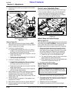
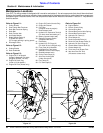
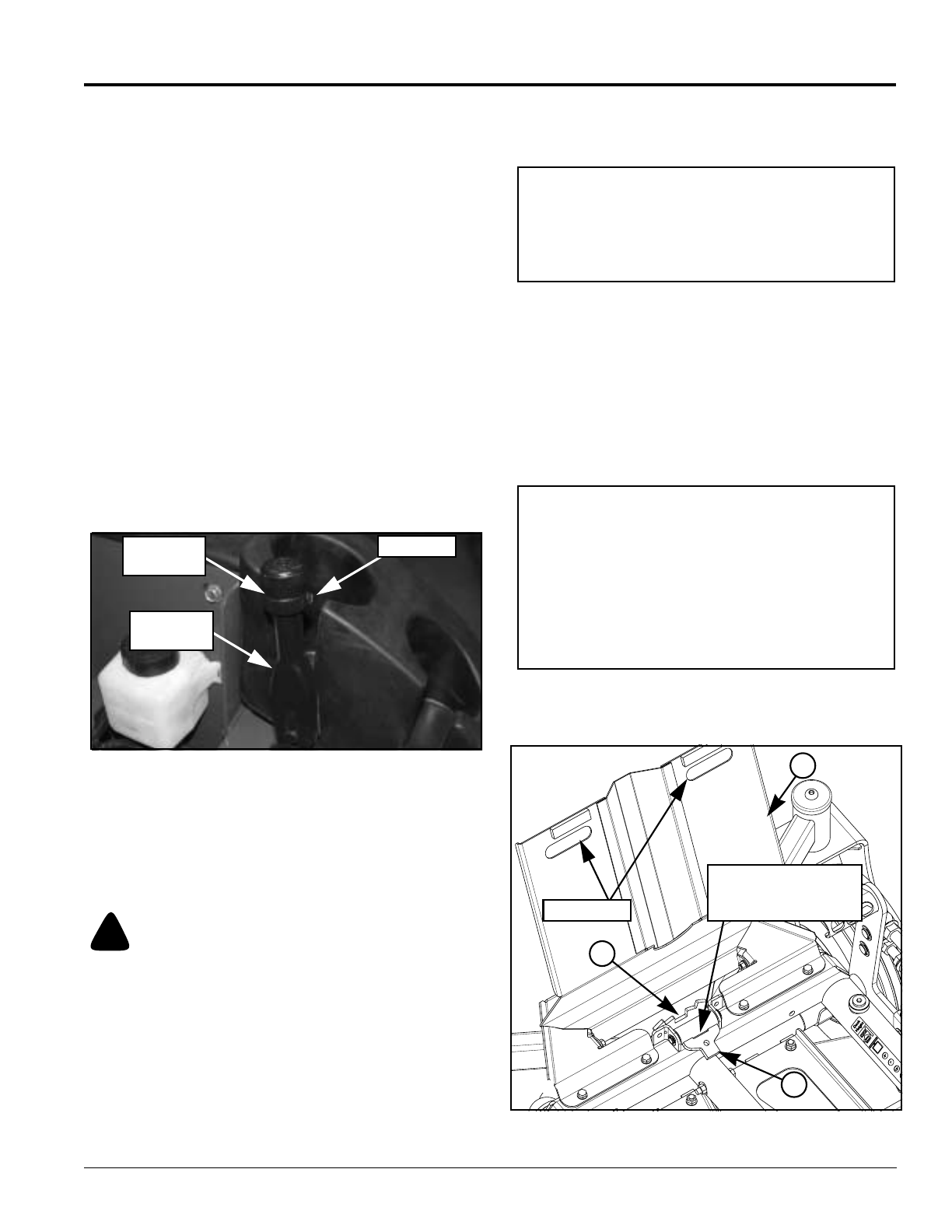
Park Brake Adjustment
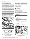
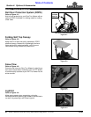
Refer to Figure 3-16:
The park brake on your mower is factory adjusted and
should not require any additional adjustments. However,
the knob on the end of the lever may be turned to make
minor adjustments if the park brake will not hold the
mower on an incline or if the park brake lever pulls too
hard (8 lbs. or more pulling force.)
1. Loosen the set screw at the park brake knob until the
knob can be rotated counter clockwise.
2. Rotate park brake knob in half turns
counterclockwise to decrease lever pulling force or
clockwise to increase lever pulling force.
3. Test pulling force by pushing off and then pulling on
the park brake. Less than 5 lbs of pulling force is
required to hold the mower on an incline. Pulling
forces of 30 lbs and higher can damage the wheel
motors.
4. Align set screw in knob with hole in lever and then
retighten it.
Major adjustments to the park brake should be made by
your nearest Land Pride Dealer.
Park Brake Adjustment
Figure 3-16
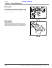
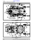
Front Axle Pivot
Refer to Figure 3-17:
The front center pivot axle can be locked to hold the front
wheels rigid or unlocked to let the front wheels float with
the contour of the ground.
!
WARNING
Make sure blade engagement switch is (OFF), switch key is
(OFF) and removed, control levers are (OUT) and park brake
is (ON) before making adjustments.
Lock Front Axle Pivot
Refer to Figure 3-17:
1. Park all four wheels on a flat level surface.
2. Be sure to adhere to the WARNING above before
opening the floor plate (#1).
3. Raise floor plate up to access pivot locking
components.
Set Screw
Park Brake
Knob
Park Brake
Lever
4. Rotate locking bar (#2) into pivot notch (#3). See
note below if locking bar does not align with notch.
5. Close floor plate.
Unlock Front Axle Pivot
Refer to Figure 3-17:
1. Park all four wheels on a flat level surface.
2. Be sure to adhere to the WARNING above before
opening the floor plate (#1).
3. Raise floor plate up to access pivot locking
components.
4. Rotate locking bar (#2) out of pivot notch (#3). See
note below if locking bar does not release easily.
5. Once free, rotate locking bar 180
o
away from the
pivot notch for storage.
6. Close floor plate.
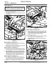
Pivot Locking Device (Unlocked Pivot Shown)
Figure 3-17
NOTE: It is not necessary for the locking bar to align
perfectly with the pivot notch. Driving the mower
after closing the floor plate will pivot the axle and
align the pivot notch with the locking bar. When
aligned, the locking bar will, on its own, fall into the
notch.
NOTE: A small pry bar or standard screwdriver can
be inserted into the opening shown in Figure 3-17 to
assist pulling locking bar out of pivot notch.
If pry bar will not dislodge locking bar, then look on
both sides of locking bar for a gap between locking
bar and pivot notch. Place a small wedge under the
front wheel that is on the same side as the gap. Try
using the pry bar again to remove locking bar from
pivot notch.
25886
1
3
2
Opening For Inserting
a Small Pry Bar or
standard screwdriver
Hand Holds