


28
Section 3: Adjustments
ZXT54 & ZXT60 Pro Series Zero Turning Radius Mowers Riding Mowers 357-271M
2/10/09
Land Pride
Table of Contents
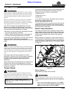
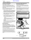
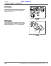
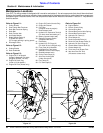
Refer to Figure 3-14:
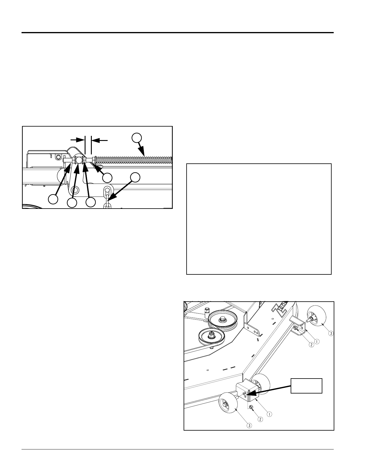
18. Adjust spring tension nut (#19) against deck lift
assist spring (#12) until there is a 1” space between
jam nut (#11) & tension nut (#19) Typical both sides.
19. When completed, all chains will be tight, deck will still
be resting on the 3" support blocks and stop handle
will be against deck height adjusting stop with stop
positioned in 3" hole.
20. Raise deck fully up until the stop handle catches on
the cross notch in the deck height gauge bar.
21. Remove all 3" support blocks.
Deck Lift Assist Spring Adjustment
Figure 3-14
Cutting Height Settings
Refer to Figure 3-11 on page 27:
Cutting height is adjustable from 1" to 5" in 1/4”
increments. The holes in the height adjusting bar (#6) are
spaced at 1/2” intervals. By turning the height adjusting
stop (#5) around, 1/4” increments can be attained due to
the 1/4” plate thickness that is part of the stop.
EXAMPLES:
1. When height adjusting stop (#5) is placed in one of
the holes with the 1/4" plate facing forward, the
cutting height will be the same as indicated on the
deck height indicator:
1, 1 1/2, 2, 2 1/2, 3, 3 1/2, 4, 4 1/2 or 5".
2. When height adjusting stop (#5) is placed in one of
the holes, with the 1/4" plate facing rearward (against
stop handle #4), the cutting height will be 1/4" more
than the deck height indicator:
1 1/4, 1 3/4, 2 1/4, 2 3/4, 3 1/4, 3 3/4, 4 1/4 or 4 3/4".
The notch located at the rear of the deck height gauge
bar (#6) is used when placing the deck in transport
position.
Cutting Height Adjustment
Refer to Figure 3-11 on page 27:
When level, the bottom edge of the deck should be 3"
above ground level with deck height adjusting stop (#5)
set at 3 1/4” cutting height. If not, readjust deck height
adjusting nut (#2) as follows:
1. Loosen jam nut (#3) and back it away from deck lift
block (#1) several turns.
25871
1” Between nuts 11 & 19
14
19
11
10
9
12
2. Turn adjusting nut (#2) against or away from deck lift
block (#1) until deck height is 3" above ground.
3. Tighten jam nut (#3) against the deck lift block (#1).
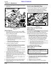
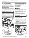
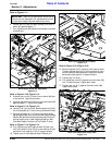
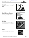
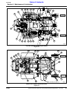
Anti-Scalp Rollers
Refer to Figure 3-15:
On the front of the mower deck are four anti-scalp
rollers (#3). Their purpose is to minimize scalping when
mowing on rough uneven terrain. Their height should be
adjusted after setting the cutting height.
1. Position mower and deck on a flat level surface.
2. Set deck at desired mowing height.
3. Remove 1/2" hex nylock nuts (#2) from all four
anti-scalp rollers (#3).
4. Reposition anti-scalp rollers up or down in the roller
mounting brackets (#1). See important note below.
5. Secure anti-scalp rollers to the mounting brackets
with 1/2"-13 hex nylock nuts (#2). Tighten nuts to the
correct torque.
Anti-Scalp Roller Adjustment
Figure 3-15
IMPORTANT: The anti-scalp rollers will extend
below blade cutting height the distance shown below
when mounted in the following holes:
• 3/4" below if mounted in the top holes.
• 1 1/4" below if mounted in the middle holes.
• 1 3/4” below if mounted in the bottom holes.
For protection of the deck and blades, it is best if the
rollers are mounted in the lowest possible hole
without the roller touching the ground.
For example:
If deck cutting height is set at 1", the rollers should be
mounted to the top holes.
If deck cutting height is set at 2" or more, the rollers
should be mounted to the bottom holes.
Adjusting
Holes
23922