


14
RTR12 & RTA12 Series (Serial No. 884764-) Rotary Tillers 311-785M
8/12/14
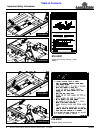
Section 1: Assembly and Set-Up
Table of Contents
!
DANGER
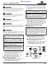
Do not engage tractor PTO while hooking-up and unhooking
driveline or while someone is standing near the driveline. A
person’s body and/or clothing can become entangled in the
driveline resulting in serious injury or death.
!
WARNING
Do not use a PTO adaptor with a quick hitch. A PTO adapter
will increase strain on the tractor’s PTO shaft resulting in
possible damage to shaft and driveline.
!
DANGER
All guards and shields must be installed and in good working
condition at all times during tiller operation.
!
WARNING
Always disengage PTO, put gear selector in park or set park
brake, shut off tractor, remove ignition key, and wait for all
moving parts to come to a complete stop before dismounting
tractor.
!
WARNING
Do not over speed PTO or machine breakage may result. Some
tractors are equipped with multispeed PTO ranges. Be certain
your tractor’s PTO is set for 540 rpm.
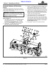
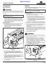
1. Park tractor and tiller on a level surface. Raise tiller to
align gearbox input shaft level with tractor PTO shaft.
Securely block tiller at this height to keep unit from
lowering while attaching the driveline.
2. Place gear selector in park, shut tractor engine off,
set park brake and remove switch key.
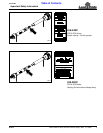
Refer to Figure 1-3 on page 11 for RTA12 or
Figure 1-5 on page 12 for RTR12
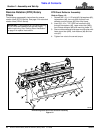
3. Remove gearbox shaft protector (#24) from end of
gearbox shaft and attach slip clutch end of
driveline (#25) to gearbox input shaft.
IMPORTANT: The driveline must be lubricated
before putting it into service. Refer to “Lubrication
Points” on page 25 for detailed instructions.
IMPORTANT: Drivelines with friction clutches must
go through a “run-in” operation prior to initial use
and after long periods of inactivity.See “Driveline
Protection” on page 22 for detailed instructions.
IMPORTANT: If tiller is to be used on more than one
tractor, an additional driveline may be required,
especially if a quick hitch is used.
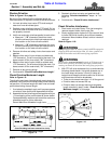
IMPORTANT: The tractor’s PTO shaft and tiller
gearbox shaft must be aligned and level with each
other during installation of driveline. This alignment
is the shortest distance between the two shafts.
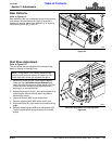
4. Attach other end of driveline to tractor PTO shaft.
5. Move driveline yokes back and forth to ensure both
ends are secured to the shafts. Reattach any yoke
that is loose.
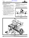
6. Attach safety chain on the outer driveline shield to
the tractor frame to restrict outer shield from rotating.
Re-latch safety chain to outer driveline shield.
7. Attach safety chain on the inner driveline shield to
the tiller frame to restrict inner shield from rotating.
Re-latch safety chain to inner driveline shield.
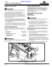
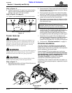
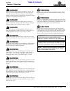
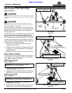
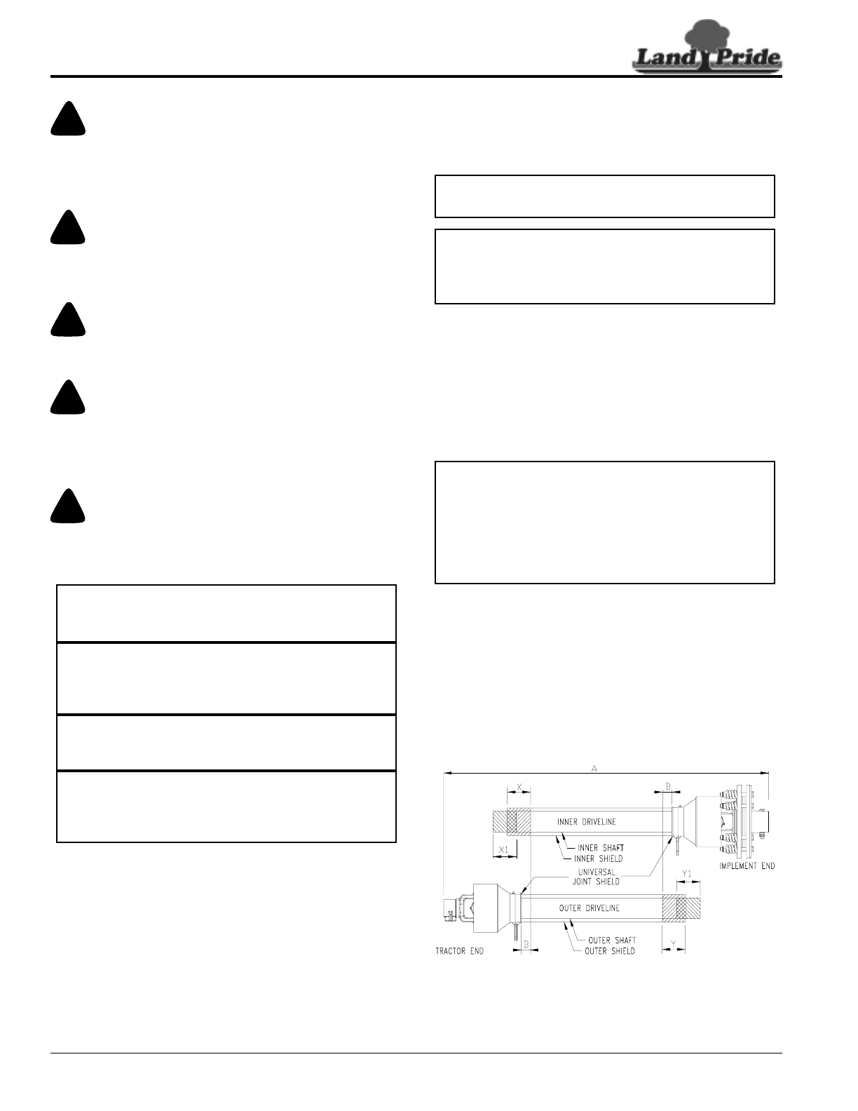
Check Driveline Collapsible Length
Refer to Figure 1-8:
1. Make sure driveline is installed properly before
checking driveline collapsed length (Refer to
“Driveline Installation” instructions on page 13).
2. With driveline level, measure 1" (“B” dimension)
back from universal joint shield to end of outer
driveline shield as shown in Figure 1-8.
a. If measurement is less than 1", shorten driveline.
a. If measurement is 1” or more, skip to “Check
Driveline Maximum Length” on page 15.
Driveline Shortening
Figure 1-8
NOTE: If driveline is too long to fit between tractor
and tiller, skip to “Shorten Driveline” on page 15.
IMPORTANT: Two safety chains are supplied with
the driveline. To keep driveline shields from rotating,
these chains must be attached to the outer and inner
driveline shields and to the tiller and tractor.
IMPORTANT: A driveline that is too long can bottom
out causing structural damage to tractor and tiller.
Always check driveline collapsed length during initial
setup, when connecting to a different tractor, and
when alternating between using a quick hitch and a
standard 3-point hitch. More than one driveline may
be required to fit all applications.
30563