


13
8/12/14
RTR12 & RTA12 Series (Serial No. 884764-) Rotary Tillers 311-785M
Land Pride
Section 1: Assembly and Set-Up
Table of Contents
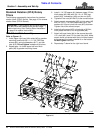
2. Secure tractor’s 3-Point lower hitch arms to the lower
hitch clevises using 7/8" diameter hitch pins. Secure
hitch pins with linch pins.
3. Secure tractor’s top center link to tiller hitch plates
using 3/4" diameter hitch pin (supplied by customer).
4. Place a level on the end plate and adjust tractor’s top
center link to level tiller from front to back.
5. Place level on the square tube and adjust one of the
two tractor’s lower 3-Point arms up or down to level
tiller from left to right.
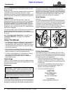
6. Raise tiller up and remove parking stand from its
mounting tube. Turn parking stand upside down and
reinsert it several inches through the top of the
mounting tube. Secure parking stand using one of
the upper three holes with existing wire retaining pin.
7. Raise tiller fully up with 3-Point lift. Measure the
distance tines are off the ground. If distance exceeds
14", adjust tractor’s 3-Point lift height limiter until
tines will not lift higher than 14 inches off the ground.
8. Continue with “Driveline Installation” on page 13.
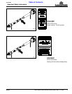
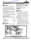
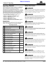
Driveline Installation
The tiller driveline is coupled to the tractor shaft with
a push-pin coupler and to the implement shaft with a
bolted coupler. A slip clutch is provided on the implement
end for protection from shock loads.
Always engage PTO at low engine rpm to minimize
start-up torque. Drivelines with friction slip clutches
must go through a “run-in” operation prior to initial
use and after long periods of inactivity. See
“Driveline Protection” on page 22 for detailed
instructions on maintaining the slip clutch.
If the Rotary Tiller is used on more than one tractor, an
additional driveline may be required - especially if a quick
hitch is used.
IMPORTANT: To keep parking stand from becoming
damaged, always store stand in the transport
position before moving tractor with tiller attached.
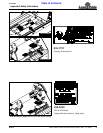
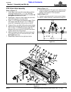
Tractor Hook-Up
Figure 1-7
30360
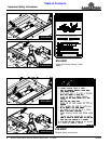
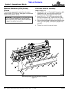
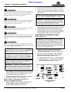
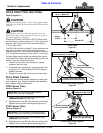
Refer to Figure 1-6:
9. Position clevises 26 7/8" apart from inside of clevis
plate to inside of clevis plate and centered off the
gearbox input shaft 13 7/16" as shown.
Refer to Figure 1-5 on page 12:
10. Tighten u-bolt locknuts (#15) to the correct torque.
Clevis Location (RTA Series Shown)
Figure 1-6
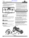
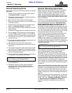
Tractor Hook-Up
!
DANGER
A Crushing Hazard exists when hooking-up equipment to a
tractor. Do not allow anyone to stand between tractor and
implement while backing-up to implement. Do not operate
hydraulic 3-point lift controls while someone is directly
behind the tractor or near the implement.
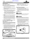
!
WARNING
Lifting unit more than 14" above ground with PTO engaged or
engaging PTO with unit higher than 14" above ground can
break the driveline and could cause flying projectiles.
!
CAUTION
To avoid bodily injury caused by accidental falling of tiller,
stabilize unit with parking stand and support blocks.
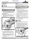
Refer to Figure 1-7:
1. Back tractor up to tiller until lower 3-Point lift arms are
aligned with tiller hitch clevises.
30349A
26 7/8"
13 7/16"