


10
RTR10 & RTR15 Series Rotary Tillers 311-431M
5/05/06
Land Pride
Section 1: Assembly and Set-Up
Table of Contents
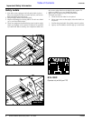
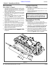
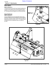
Hitch Assembly
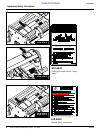
Refer to Figure 1-1 on page 9:
1. Install both top 3-point hitch plates (#1 and #2) outside
of gearbox mounting frame with 5/8” x 1 3/4” long bolts
(#3), 5/8” lockwashers (#4), and 5/8” nuts (#5). Do not
tighten hardware at this time.
2. Install spacer (#6) between upper 3-point hitch plates
(#1 & #2) with 3/4” x 4” long bolt (#7), 3/4” lockwasher
(#8) and 3/4” nut (#9).
3. Securely tighten all bolts. Refer to the Torque Values
Chart in the “Appendix” section on page 29.
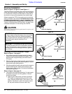
4. Mount left hand clevis (#13) over the square tube as
shown. Make certain the longer chamfer is positioned
on the bottom.
5. Locate u-bolt (#16) behind the square tube and insert
through clevis (#13) holes as shown.
6. Secure with 1/2” hex locknuts (#14). Do Not Tighten.
7. Repeat steps 4 through 6 for the right hand clevis.
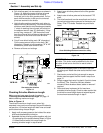
8. Position clevises 26 7/8” apart from inside of clevis
plate to inside of clevis plate and center off the
gearbox input shaft as shown.
9. Tighten 1/2” locknuts (#14) to the correct torque. Refer
to the Torque Values Chart in the “Appendix” section
on page 29.
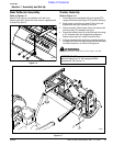
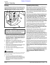
Leg Stand Assembly
Refer to Figure 1-1 on page 9:
1. Insert leg stand (#10) into leg stand holder on the end
of the tiller frame.
2. Adjust to the desired height and pin with 1/4” x 1 3/4”
long wire lock pin (#11).
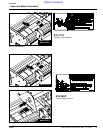
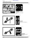
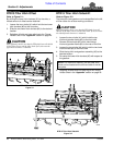
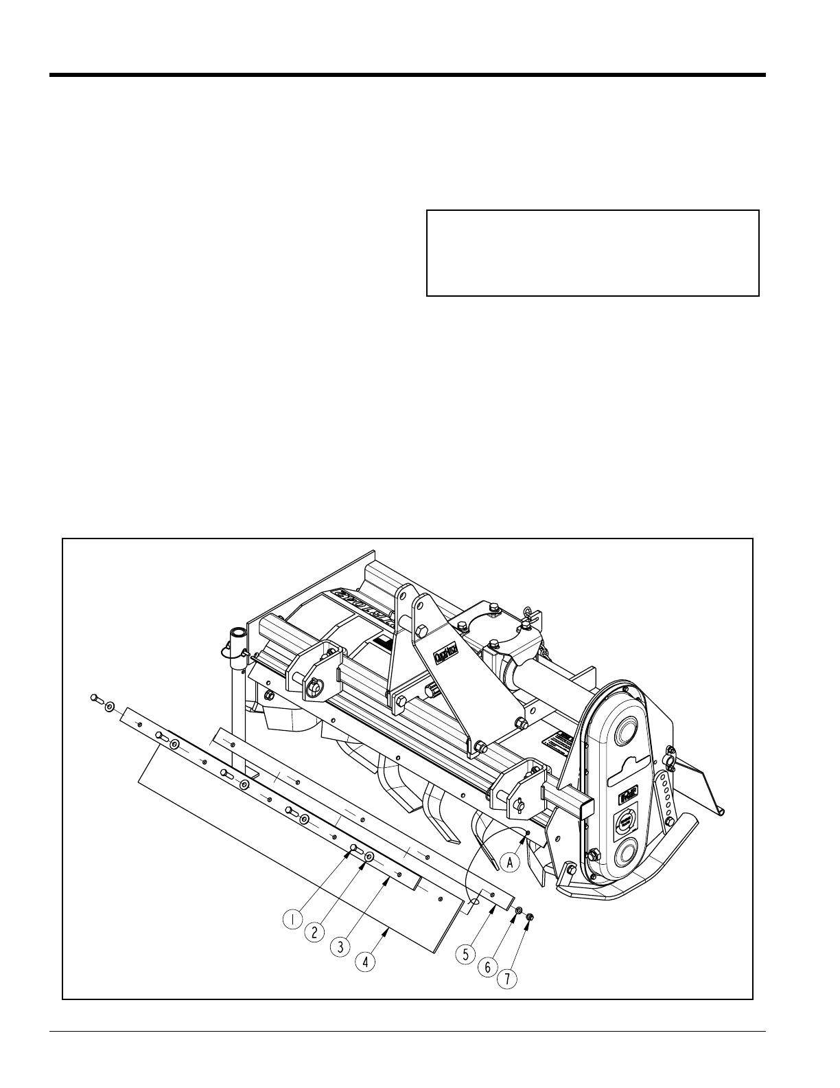
Front Deflector Assembly
Refer to Figure 1-2
1. Remove 3/8” x 1 1/2” bolts (#1), washers (#2),
lockwashers (#6), hex nuts (#7) and two front deflector
mounting bars (#3 & #5) from the tiller frame.
2. Insert 3/8” x 1 1/2” hex head bolts (#1) through 3/8” flat
washers (#2), upper front deflector mount bar (#3),
front rubber deflector (#4) and mounting holes “A”.
3. Secure to tiller with lower front deflector mount bar
(#5), 3/8” lock washers (#6) and 3/8” hex nuts (#7).
4. Securely tighten all bolts. Refer to the Torque Values
Chart in the “Appendix” section on page 29.
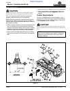
IMPORTANT: The three upper holes in the leg stand
are used for parking the tiller. Before tilling, remove leg
stand from holder, turn leg stand upside down and
replace it through the top of the holder. Secure leg
stand in holder using one of the upper three holes.
Figure 1-2
22253