


11
Section 1 Assembly and Set-Up
12/14/01
RCR16 Series Rotary Cutters 312-742M
Land Pride
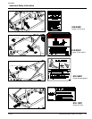
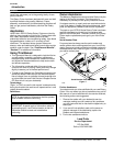
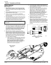
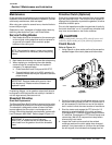
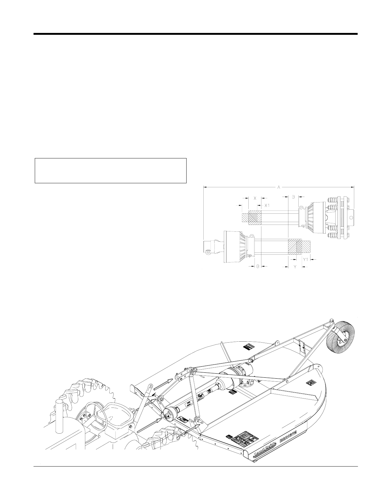
b. Pull driveline apart. Reattach outer sections to
tractor and gearbox. Pull on driveline section to be
sure that yoke locks into place.
c. Hold driveline sections parallel to each other to
determine if too long. Each section should end
approximately 1" ("B" dimension) short of
reaching universal joint shield on opposite
section. If too long, measure 1" ("B" dimension)
back from universal joint shield and mark on
opposite section. Do this for both sections.
d. Cut off shield where marked ("X" dimension). Cut
shaft the same amount ("X" dimension).
e. Repeat the procedure to the other driveline half.
Remove all burrs and cuttings.
f. Apply multi-purpose grease to inside of outer
(female) driveline section. Assembledriveline and
install on tractor and cutter. Pull on each driveline
section to be sure yokes lock into place. Make
certain driveline shielding is in place and in good
condition.
Shortening Driveline Shafts
Figure 1-8
18347
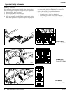
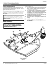
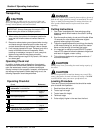
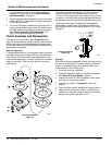
Tractor Hook-Up
Figure 1-7
19747
Tractor Hook-Up
Refer to Figure 1-7:
1. Slowly back the tractor up to the cutter and use the
tractor’s 3-point hydraulic control to adjust the lower
link arms up or down to match the height of the cutter
hitch pins.
2. Simply position the lower link arms to "insert" the hitch
pin into the lower hitch link hole.
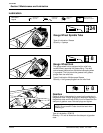
3. Install a linch pin or other fastener (supplied by
customer) through the hitch pin hole to lock the lower
links into position.
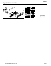
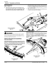
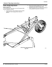
4. Connect the driveline to the tractor’s PTO output shaft
and secure with locking device on driveline. Connect
the safety chain to the hitch brace on the cutter to
restrict outer shield of driveline from rotating.
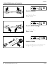
5. Connect the top link to the upper pivot hitch using the
3/4" clevis pin supplied. In most cases, the lowest hole
of the upper pivot hitch is the appropriate hole to use.
For tractors with shorter than normal top-links, the
second set of holes on the upper pivot hitch allows
greater ground clearance for the tailwheel.
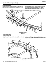
6. Start the tractor and slowly engage the tractor’s
hydraulic 3-point to lift the cutter. Check for sufficient
drawbar clearance. Move the drawbar ahead, aside or
remove if required. Watch the telescoping movement
of the driveline to ensure that it does not bottom out
while lifting the 3-point. If the driveline does bottom
out, it will require shortening:
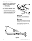
a. Refer to Figure 1-8. Raise the tractor 3-point hitch
so the input shaft of the cutter gearbox is in line
with the PTO shaft on the tractor. Shut down
tractor, leaving cutter in position of shortest
distance between shafts, refer to "A" dimension.
Securely block cutter in position. Remove
driveline from tractor and gearbox
NOTE: Chain should be attached at implement end
of driveline.