


7
Section 1: Assembly & Set-up
10/29/08
GS2584 & GS2596 Grading Scrapers 303-268M
Land Pride
Table of Contents
Section 1: Assembly & Set-up
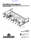
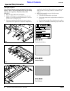
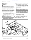
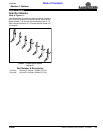
Hitch and Shank Set-up
Figure 1-1
26655
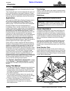
6. Place hitch braces (#2) inside hitch straps (#3 & 4).
Place 2" long spacer (#6) between hitch braces and
insert 3/4"-10 x 5" GR5 hex head cap screw (#8)
through hitch straps, hitch braces and spacer as
shown. Secure assembly with 3/4" lockwasher (#10)
and 34" hex nut (#9).
7. Tighten all 3/4" bolts (#7 & 8) to the correct torque.
Make sure hitch pins (#5) are loose. If not, readjust
hitch frames (#3 & 4) and retighten bolts (#7 & 8).
8. Install 3/4" x 3 3/4" hitch pin (#13) to hitch straps and
secure in place with hairpin cotter (#14).
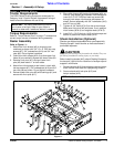
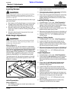
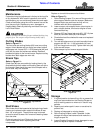
Shank Installation (Optional)
Shanks are shipped assembled when purchased with
Grading Scraper. Install shanks as instructed below if
purchased separate.
!
CAUTION
Keep your feet and legs out from under the shanks. They can
fall during installation causing injury to your body.
Before installing shanks (#16), attach Grading Scraper to
the tractor’s 3-point hitch or raise front of scraper up and
support it with blocks.
1. Remove shanks (#16) from shipping crate and insert
them into the front slots with tips pointing forward.
2. Secure shanks with lock pins (#15) and
hairpin cotters (#12).
NOTE: See Section 2: Adjustments for shank depth.
Tractor Requirements
The GS25 Series Grading Scrapers are designed for
Category l and ll 3-point hitches. Horsepower rating of
tractor should be between 40 and 90 hp.
Torque Requirements
Refer to “Torque Values Chart” on page 17 to determine
correct torque values or fasteners during assembly.
Dealer Assembly
Refer to Figure 1-1:
1. Attach rear hitch braces (#2) to channel cross
members as shown with 3/4”-10 x 2" GR5 hex cap
screws (#7), 3/4” lockwashers (#10) and 3/4” hex
nuts (#9). Do not tighten hardware.
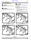
2. Orient front hitch straps (#3 & 4) so that upper link
holes (A) are vertically aligned with lower holes (B).
3. Remove linch pins (#11) and pull lower hitch
pins (#5) back about 1" on both sides.
4. Attach front hitch straps to rear holes in clevis with
hex cap screws (#7), 3/4” lockwashers (#10) and 3/4”
hex nuts (#9) as shown. Do not tighten hardware.
5. Reinsert lower hitch pins (#5) with bushings (#1) and
secure with linch pins (#11).
IMPORTANT: You could loose steering control if
your tractor is too light. Refer to your tractor’s
manual to determine if additional ballast is needed.