


11
Section 1: Assembly and Set-Up
10/15/07
FDR2572 & FDR2584 Grooming Mowers 310-262M
Land Pride
Table of Contents
Driveline Installation
An additional driveline may be required if the Grooming
Mower is used on more than one tractor especially if a
quick hitch is used.
!
CAUTION
Do not use a PTO adaptor with a quick hitch. A PTO adapter
will increase strain on the tractor’s PTO shaft resulting in
possible damage the shaft and driveline.
!
WARNING
Damaged drivelines can cause serious injury or death.
!
CAUTION
Tractor PTO shield and all Grooming Mower guards must be
in place at all times during operation!
!
CAUTION
Always engage parking brake, shut off tractor and remove key
before dismounting from tractor.
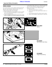
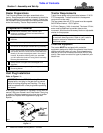
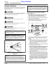
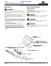
Maximum Allowable Driveline Movement
Figure 1-5
IMPORTANT: Some tractors are equipped with
multispeed PTO ranges. Be certain your tractor ‘s
PTO is set for 540 rpm.
IMPORTANT: Avoid premature driveline
breakdown. A driveline that is operating must not
exceed an angle of 25 degrees up or down while
operating the 3-point lift. See Figure 1-5 below.
24872
IMPORTANT: Always check driveline minimum
length during initial setup, when connecting to a
different tractor and when alternating between using
a quick hitch and a standard 3-point hitch. More than
one driveline may be required to fit all applications.
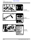
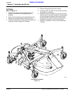
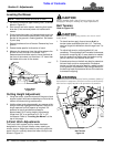
Checking Driveline Minimum Length
Refer to Figure 1-6:
1. Start tractor and slowly engage 3-point controls to
move lower arms until the gearbox shaft is
approximately level with the tractor's PTO shaft.
2. Slide inner yoke of driveline over the gearbox shaft
and secure with locking collar.
3. Slide outer yoke of driveline over the tractor PTO
shaft and secure with locking collar.
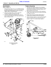
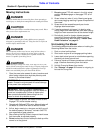
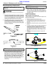
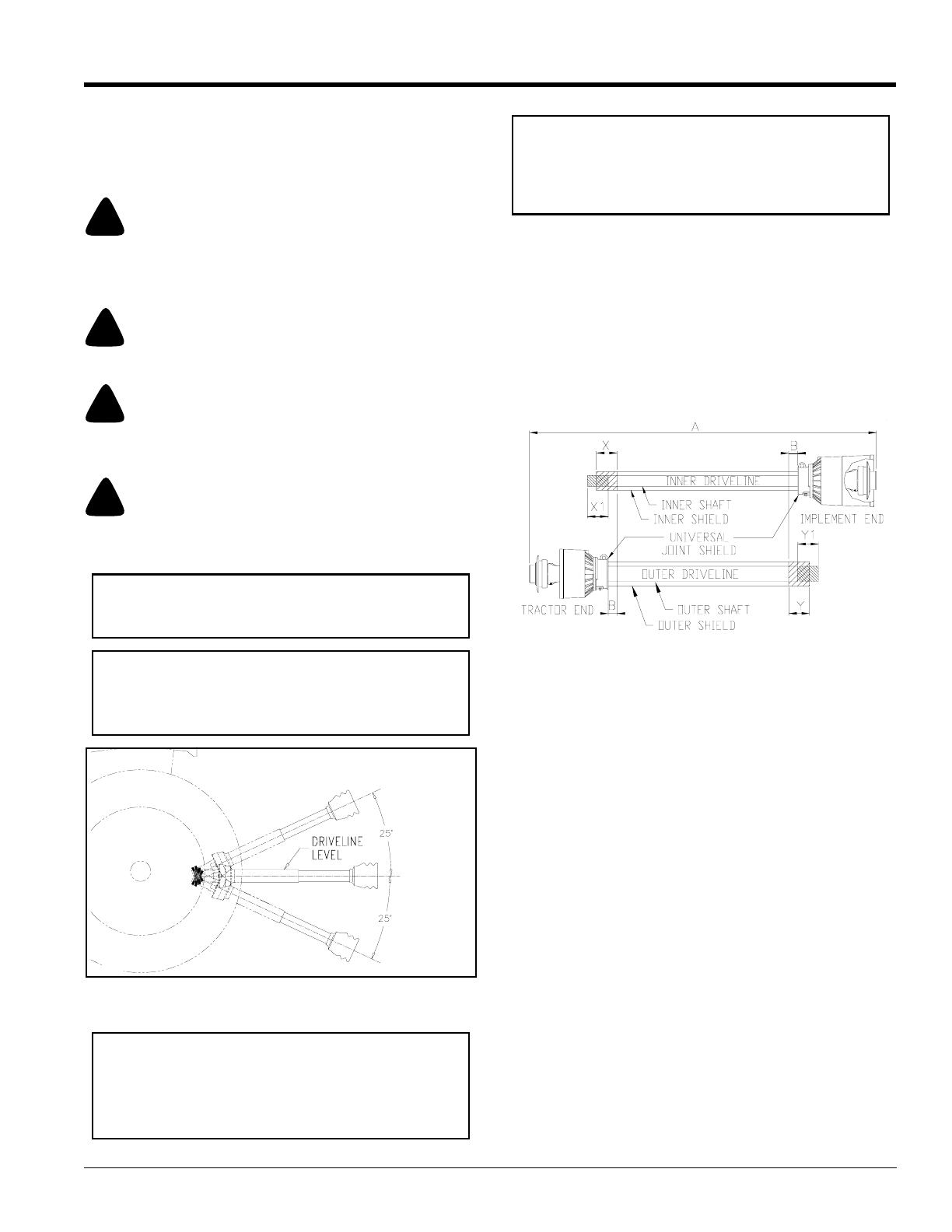
Driveline Shortening
Figure 1-6
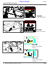
4. The driveline will require shortening if it does not fit
between tractor and mower. Shorten driveline as
follows:
a. Raise or lower 3-point lower arms until mower and
tractor PTO shafts are approximately level with
each other. Securely block Grooming Mower
frame in this position.
b. Set tractor in park, shut tractor engine off, set park
brake and remove switch key.
c. Pull driveline apart into two sections as shown in
Figure 1-6. Attach outer driveline universal joint to
the tractor PTO shaft. Attach inner driveline
universal joint to the gearbox shaft. Pull on each
driveline section to be sure universal joints are
secured to the shafts.
d. Hold driveline sections parallel to each other to
determine if they are too long. The inner and outer
shields on each section should endapproximately
1" short of reaching the universal joint shield on
the adjacent section (see “B” dimension). If they
are too long, measure 1" (“B” dimension) back
from the universal joint shield and make a mark at
this location on the inner and outer driveline
shields.
IMPORTANT: Itis necessary to aligning the tractor’s
PTO shaft level with the Grooming Mower’s gearbox
shaft when checking driveline minimum length. Too
long a driveline can damage tractor, gearbox and
driveline.
22009