


TP-6905 6/14 27Section 2 Generator Set Operation
2.6.5 Event Log
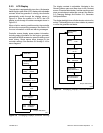
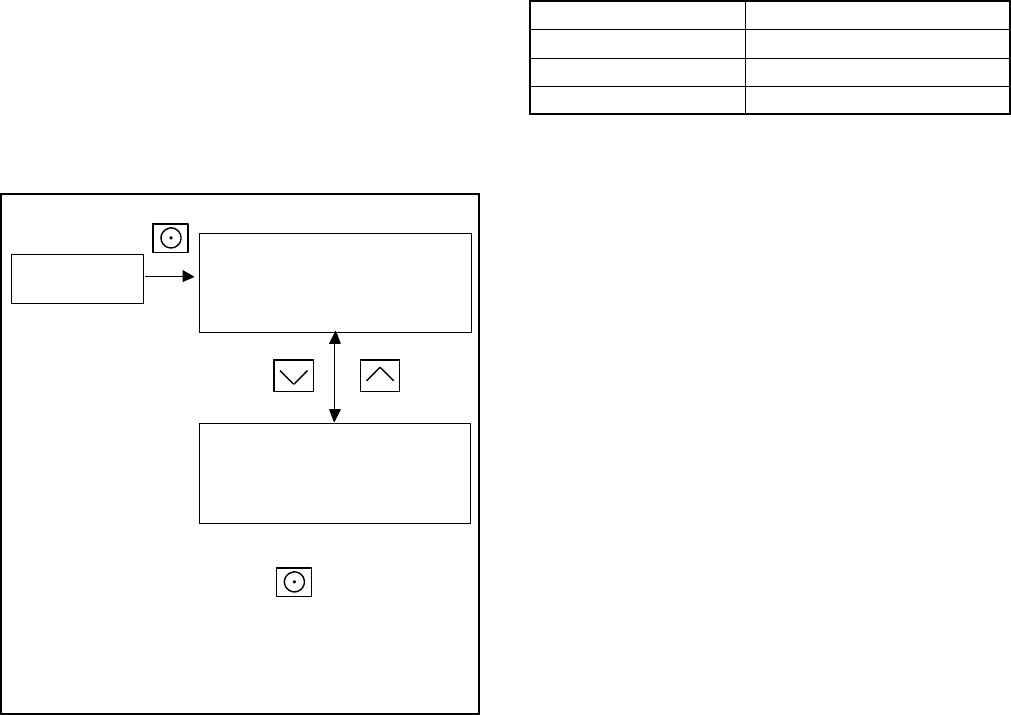
The event log displays up to 1000 controller faults and
notices, starting with the most recent event. Events are
numbered 1--1000, with 1 being the most recent. Each
event is displayed with the date and time of the event,
the number of the event, a code to indicate whether the
event was a warning (W), shutdown (S), or
informational notice (I), the engine hours at the time of
the event, and the event description.
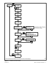
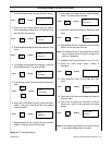
Procedure to View Event History
1. Press Select to enter the main menu.
2. Pressthedownarrowto stepdowntothe eventlog.
3. Press Select to display the most recent event.
4. Press the down arrow to step to the next event.
5. Use the up and down arrowbuttons to view events.
6. Press the Select button to exit the event log.
To stop viewing the event history before the last event,
press the select button to return to the main menu.
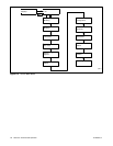
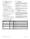
tp6810
Event Log ---->
Date MO/DA/YEAR
time HR:MN
event number, W/S/I, engine hours
event name
Press UP and Down arrow
buttons to scroll through events
Date MO/DA/YEAR
time HR:MN
event number, W/S/I, engine hours
event name
Press Select button at any time to
return to the main menu.
Event codes:
W=Warning
S = Shutdown
I = Informational Notice
Figure 2-6 Event Log
2.7 Model RXT Transfer Switch
Operation
The RDC2 generator set/transfer switch controller
manages automatic transfer switch (ATS) functions
whenconnectedtoaKohlerrModelRXTtransferswitch
through the ATS interface board. Refer to the Model
RXT Operation/Installation Manual for information
about the transfer switch operation.
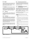
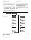
2.7.1 Source Availability
The Model RXT transfer switch supplies voltage
sensing data to the RDC2 controller through the ATS
interface board. If the source voltage falls below the
undervoltage dropout setting, the source is considered
to have failed. See Figure 2-7.
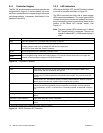
Item Setting
Accuracy ±5%
Undervoltage Dropout 90% of Pickup
Undervoltage Pickup 90% of Nominal
Figure 2-7 Voltage Sensing Parameters
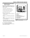
The RDC2 controller also has a set of power system
LEDs below the pushbuttons. The power system LEDs
indicate which power sources are available and which
source is supplying power to the building. See
Figure 3-1.
Note: The power system LEDs operate only if a Model
RXT transfer switch is connected. They will not
operate if a Model RDT or RSB transfer switch is
used.