


Installation Instructions
OUCC002,00021CA –19–18NOV06–5/8
IMPORTANT: Route wiring harness AZ101120 (C)
alongside machine wiring harness
and secure with tie bands.
NOTE: Connector (A) shall be used for inoculant
dosing device connection.
Connector (B) shall be stored in a safe place if
NIR sensor is not installed on spout.
NOTE: Use the existing machine wiring harnesses
and/or hydraulic hoses to fix the wiring
harness AZ101120 (C) with plastic clamps so
that it will not be left loose in a way it can be
caught by any moving part.
OUCC002,00021CA –19–18NOV06–6/8
ZX1037996 –UN–13SEP05ZX1037997 –UN–13SEP05
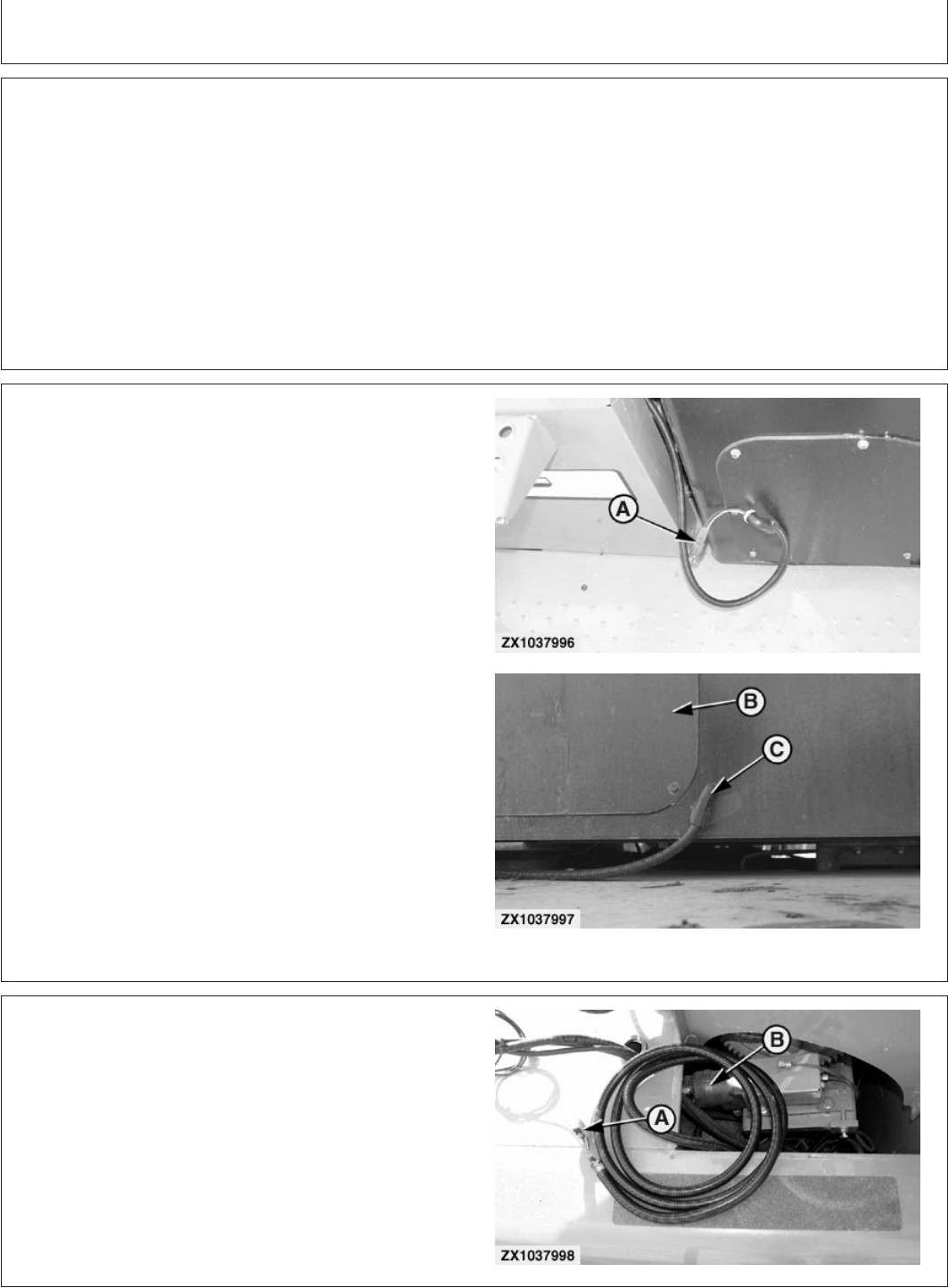
A—Connector for inoculant dosing device
B—Closing plate
C—Connector sleeve
8. Route inoculant dosing device connector (A) outside
the rear right-hand side of the cab as shown.
9. Drill a suitable hole near the cab closing plate (B) so
that connector sleeve (C) can be inserted and fixed to
the cab wall as shown.
IMPORTANT: Open plate (B) and check that no wiring
harness is being damaged while drilling
the hole!
-If an inoculant dosing device is used, route dosing
device connecting wires through opening of closing
plate and refer to “Connecting Inoculant Dosing
Device” for proper device connection.
-If no inoculant dosing device is used, keep connector
(A) protected behind closing plate (B).
OUCC002,00021CA –19–18NOV06–7/8
ZX1037998 –UN–13SEP05
A—NIR sensor connector
B—Spout motor
10. In Case Bundles BZ100157 and BZ100165 are Not
Installed on Spout:
Route and store NIR sensor connector (A) near the
spout motor (B). Make sure to store the cable so that
it will not be caught by any moving part.
Z103757 (13DEC06)
19
Installation Instructions
011507
PN=21
Continued on next page