J-200
The rst press activates high speed, the second press turns jets pump 2
off. When manually activated, either pump will automatically turn off after
20 minutes.
10.3 Standard Light Operation
The light button activates the footwell light in the spa when
pressed. Pressing the button turns the footwell light off. When
manually activated, the footwell light will automatically turn off
after one hour.
10.4 Optional Multi-Colored LED Light System Operation
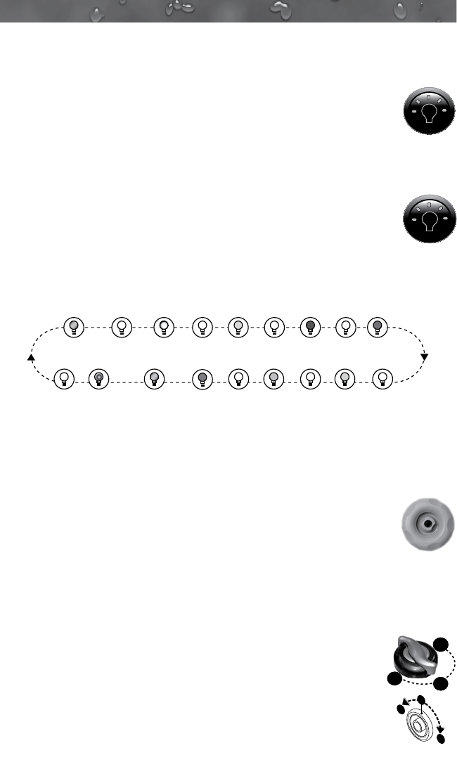
The multi-colored LED spa light offers seven constant color
variations and three unique random modes for enhanced spa
enjoyment. Press the Light button once to activate the rst light
mode Random Fade, then continue pressing the button to
either turn the light off or to select one of seven constant colors,
random solid color mode or strobe mode as illustrated below.
Spa Light Sequence
DARK
GREEN
DARK
BLUE
RED
LIME
GREEN
OFF
RANDOM
FADE
RANDOM
SOLID
STROBE
OFF
OFF OFFOFFOFF
OFF OFF
NEAR
WHITE
VIOLET
LIGHT
BLUE
Light Operation Tips:
You must press the light button within 3 seconds of any “off” condition or the
light sequence will revert back to “Random Fade” mode, when reactivated.
Anytime the spa light is manually activated, it will remain on for 1 hour
then automatically shut off.
10.5 Adjusting Individual Jet Flow
The water ow through individual jets in your spa can be
adjusted or turned off by rotating the outside jet ring. Many jets
also offer an adjustable center nozzle that allows you to change
the water discharge angle. Simply tilt the center nozzle in these jets to the
desired angle to customize your personal massage.
Note: Always keep at least 6 adjustable jets open at all times to ensure
proper ltration characteristics within spa.
10.6 Selecting Desired Massage Action
All models incorporate a massage selector (Diverter Jet for
J-210, Figure A) valve that allows you to customize the mas-
sage and performance by diverting water between various jet
systems within the spa. Simply turn valve to positions A, B or
C to divert water pressure to various jet groups.
Note: The valve is intended to operate in positions A
(Combo), B, or C for optimum performance. It is consid-
ered normal for sound levels within the valve to increase be-
tween these positions due to the large amounts of water owing through
B
A
C
A
B
C
Figure A
27


