


Jacuzzi
©
Chromatherapy: Installation and Operation Page 3 of 5 GQ99000 • 07-08
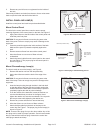
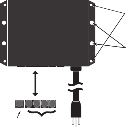
Figure 5. Control Box Connections
3-Prong power cable
No. 20, 1/4”
Screw hole
(2 both sides)
No. 10 Screw hole
(2 both sides)
Modular plug
for control panel
Modular plugs
for lamps (1 to 4)
mount the ControL Box
Mount the control box to a stud beam or secure wall using four
No. 10 screws, or four No. 20, 1/4 inch screws. The mounting
holes for the screws are shown in Figure 5.
note: The modular plugs are also shown in the gure. Position
the control box in the most advantageous way, considering the
length and direction of the modular cables.
Caution: The power cable must be connected to a dedicated
ground fault circuit interruptor (GFCI). No other outlet is
acceptable to this equipment.
Attach the control box securely to the mounting location.
driLL the hoLes
After preparation of the bath shell for drilling the hole for the
control panel and each Chromatherapy lamp, proceed with drilling
the holes. This should be completed by a technican experienced
in drilling through a ne acrylic material.
The areas of the holes have been covered with masking tape and
carefully outlined to indicate the location and size of the holes.
The tape will help prevent chipping of the acrylic.
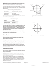
Drill Hole for the Control Panel
The control panel has been located a minimum of one inch
above the level of the overow drain. It has been marked for a
1-1/16 inch diameter with a 5/32 inch notch at the right center, see
Figure 3.
Caution: Drill the holes from the inside of the unit carefully
to prevent chipping or cracking of the acrylic shell. Use a drill
guide for best results and begin drilling at low speed until the
drill penetrates the acrylic layer, then use a high speed for the
remaining material.
1. First use a 5/32 inch drill bit to carefully drill the notch.
2. Use the 5/32 inch drill bit to drill a pilot hole for the
1-5/8 inch hole.
3. Use a 1-1/16 inch drill bit to complete the hole for the lamp.
4. Remove any and all burrs or roughness from the inside of
the hole.
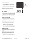
Drill Hole for the Lamp(s)
The lamp(s) has been located a minimum of 4 inches below the
normal water level. It has been marked for a 1-5/8 inch diameter,
see Figure 4.
Caution: Drill the holes from the inside of the unit carefully
to prevent chipping or cracking of the acrylic shell. Use a drill
guide for best results and begin drilling at low speed until the
drill penetrates the acrylic layer, then use a high speed for the
remaining material.
1. Use the 5/32 inch drill bit to drill a pilot hole for the 1-1/16
inch hole.
2. Use a 1-5/8 inch drill bit to complete the hole for the control
panel.