


Page 41
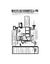
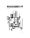
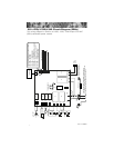
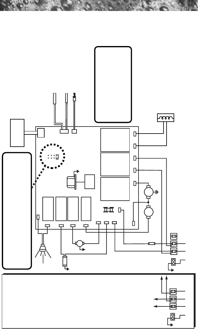
15.0 J-310 Convertible Circuit Diagram (60Hz)
This wiring diagram is used for the J-310 US/Canada 120/240 VAC (60Hz)
convertible power model.
Ozonator
O
3
GRN
TB1
Standard 120 VAC 3-Wire Connection
(60 Hz, 1 Phase, 15 A Service)
Use copper conductors ONLY. Wire size must be
appropriate per NEC and/or local codes.
WHT
WHT
WHT
WHT
WHT
BLK
BLK
RED
BLK
BLK
BLK
BLK
BLK
RED
RED
RED
BLK
321
Heater
1.0 kW @ 120 VAC
4.0 kW @ 240 VAC
Flow Switch
Hi-limit/Freeze
Sensor
Temperature Sensor
J2
J3
F1
20A
250V
SC-20
Circ.
Pump
Main
Pump
Spa Light
Transformer
120 VAC
J4
BLK
RED
*
GRN
TB1
WHT
BLK RED
321
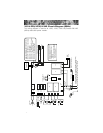
Optional 120/240 VAC
4-Wire Convertible
Heater Connection
1. Remove and discard the
factory installed GFCI Cord.
2. Move RED* wire from TB1
position #1 to TB1 position #3
as shown below.
3. Permanently connect to
the power supply. Use
copper conductors ONLY.
Wire size must be
appropriate per NEC and/or
local codes.
4. If hot tub is to be operated
on 30A service, make sure
the jumper provided at
location JP1 #1&2 on the
circuit board is installed. If
hot tub is to be operated on
40A service, remove the
jumper JP1 #1&2 on the
circuit board.
HILO
JP1
4
2
3
1
65
87
Logic Jumper Settings (Factory Defaults Shown)
JP1 1-2 ON = 15A Logic (3-wire 120 VAC operation only)
JP1 1-2 ON = 30A Logic (4-wire 120/240 VAC operation only)
JP1 1-2 OFF = 40A Logic (4-wire 120/240 VAC operation only)
JP1 7-8 ON = ¡C Temperature Display
JP1 7-8 OFF = ¡F Temperature Display
This device complies with Part 15 of the
FCC rules. Operation is subject to the
following two conditions:
1. This device may not cause harmful
interference.
2. This device must accept any inteference
received including interference that may
cause undesired operation.
J20
J21
J12
J14
J16
J11
J15
J13
J17 J7 J8 J9 J10
J5
J6
Heater IN Heater OUT
F1*
K1
K2
K3
K4
K5 K7 K8
J1
Control
Panel