


Page 11
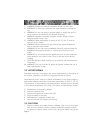
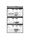
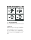
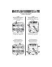
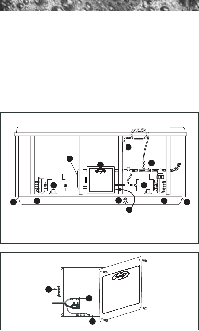
Figure-B - Control Box
1. Terminal Block
2. Bonding Lug
3. Grounding Terminal
TB1
3
2
1
9
10
4
37
1
2 2
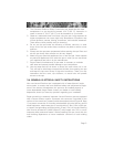
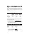
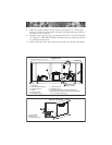
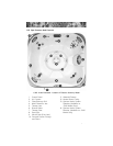
Figure-A
Equipment Area
1. Control Box
2. Power Supply Entrance(s)
3. 2-Speed Pump #1
4. Heater
5. Spa Drain Valve
6. Pump Drain Plug(s)
7. 1-Speed Pump #2
8. Circulation Pump
9. Optional CD Ozonator (Purchased Separately)
10.Optional Mazzei Injector (Required for CD Ozonator
Use - Purchased Separately)
Flow
Note: Pump Locations Vary by Model
Circulation Pump
Behind Load Box
8
5
6 6
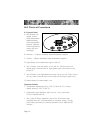
8. Select the power supply inlet you want to use (Figure A). Feed power
cable to control box, then install it through the large opening provided in
the bottom side of the box.
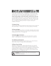
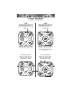
9. Connect wires, color to color, on terminal blocks TB1 and TB3 (Figures
C-F, Page 12). TIGHTEN SECURELY! All wires must be hooked up secure-
ly or damage could result.
10. Install control box door and screws and reinstall the cabinet side panels.