10
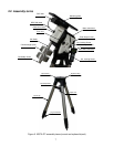
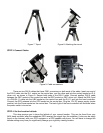
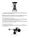
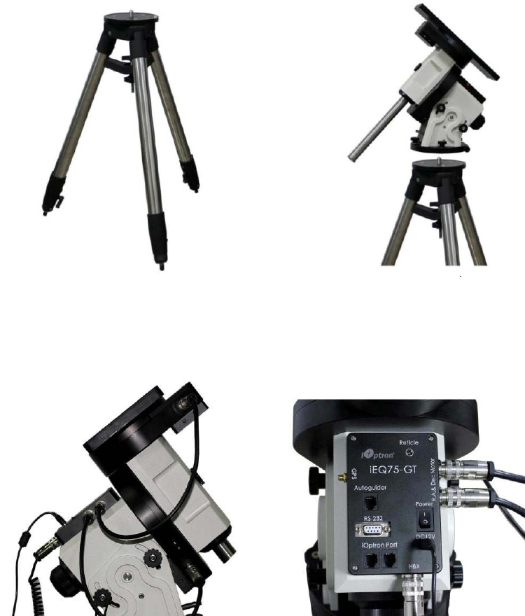
Figure 7. Tripod
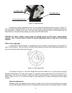
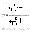
Figure 8. Attaching the mount
STEP 3. Connect Cables
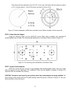
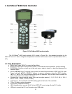
Figure 9. Cable connections
There are two DIN 6 cables that have C091 connectors on both ends of the cable. Insert one end of
the DIN 6 cable into the R.A. socket on the control box, and the other end into the socket located on R.A.
driver unit, as shown in Figure 9. Secure both ends of the DIN 6 cable. Connect another DIN 6 cable
between the DEC socket on the control box and the DEC socket on DEC driver unit. Attach the DIN 6 end
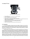
of a DIN-RJ-11 cable into the HBX socket on the control box and the RJ-11 end into the hand controller.
Connect the GPS antenna into the GPS socket on the control box. Plug the 12V DC power supply (center
positive) into the Power socket on the control box. The back light of the hand controller will illuminate when
the power switch is turned on.
STEP 4. Set the Location Latitude
This step requires you to know the latitude of your current location. This can be found from your
8406 hand controller after the embedded GPS receives the signal from the satellites. It also can be easily
found on the Internet, with your GPS navigator or a GPS capable cell phone. You will have to change this
latitude setting every time you significantly change your night sky viewing location.


