


109631_0908 4-3
Introduction
Regular maintenance is the best prevention for costly downtime or
expensive, premature repair. The following pages contain suggested mainte-
nance information and schedules which the operator should follow on a rou-
tine basis. For more detailed information refer to the correct parts manual for
your unit.
Remain alert for unusual noises, they could be signaling a problem.
Visually inspect the machine for any abnormal wear or damage. A good time
to detect potential problems is while performing scheduled maintenance ser-
vice. Correcting the problem as quickly as possible is the best insurance.
Clear away heavy build-up of grease, oil and dirt, on top of the deck and
under the deck areas especially under the deck guards.
Daily inspect mower deck for grass clippings and wire and string tangles.
The underside of the mower deck will collect a build-up of grass clippings
and dirt, especially when grass is wet or has high moisture content. This
build-up will harden, restricting blade and air movement and will probably
show a poorer quality of cutting. Therefore it should be removed routinely.
To do this it will be necessary to pivot the deck to the full up position and
scrape the build-up from underneath. See Mower Deck Tilt Procedure sec-
tion.
Some repairs require the assistance of a trained service mechanic and
should not be attempted by unskilled personnel. Consult your Hustler service
center when assistance is needed.
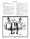
Description of operation
The three mower blades are indirectly driven by the tractor engine:
Power flows through the mechanical clutch, PTO drive shaft, right angle
gearbox, and finally through a V-belt drive system. The V-belt drives three
pulleys; each pulley is on top of a spindle housing assembly. The pulleys
drive 1” spindle shafts which in turn drive the blades. A blade is affixed to
each spindle shaft by a 5/8” bolt.
The mower deck is connected to tractor by attaching the mower tool bar
arms to the tractor tool bar with clevis pins and hairpins.
Torque values
WARNING: Particular attention must be given to tightening
the blade spindle bolts. Failure to correctly torque these items
may result in the loss of a blade, which can cause serious dam-
age or personal injury.
Torque values are given below:
Ft-lbs. Nm
Spindle blade bolt (bottom) . . . . . . . . . . . . . 118 . . . . . . . . .160.01
Spindle pulley bolt (top) . . . . . . . . . . . . . . . . 75. . . . . . . . . .101.68
For all other torques refer to the deck parts manuals for standard torque
chart.
Tires
It is important for level mowing that the tires have the same amount of air
pressure. The recommended pressure is:
Front gauge wheels . . . . . . . . . . . . . . . . . . . . . 8-12 psi (55-83 KPa)
Solid fill tires are not recommended for Hustler turf equipment. On
any machine, with solid filled tires, the warranty claim will be denied.
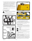
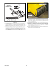
Lubrication
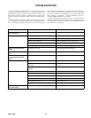
Check gearbox lubricant daily by looking at the sight gauge located on
side of gearbox. It should appear half full. Fill as necessary with ISO VG46
oil (Hustler P/N 601621). Fill by removing pipe plug located on top front of
gearbox. Add oil until the sight ball floats off of the bottom. Fig. 4-2
Spindle housing, under mower. Lubricate spindle housings annually or
after every 750 hours of operation, whichever occurs first. Use no more than
one or two ounces of multi-purpose lubricant. Do not force lubricant into
grease zerks. Bearings are sealed and do not require much lubrication.
Mower deck tilt procedure
The mower deck is designed to be raised and pinned in an upright posi-
tion to allow easier access to the underneath side of the mower deck.
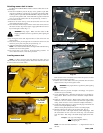
1. Park the unit on a flat surface, raise mower deck and set the parking
brake.
2. Shut off engine and remove the ignition key.
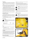
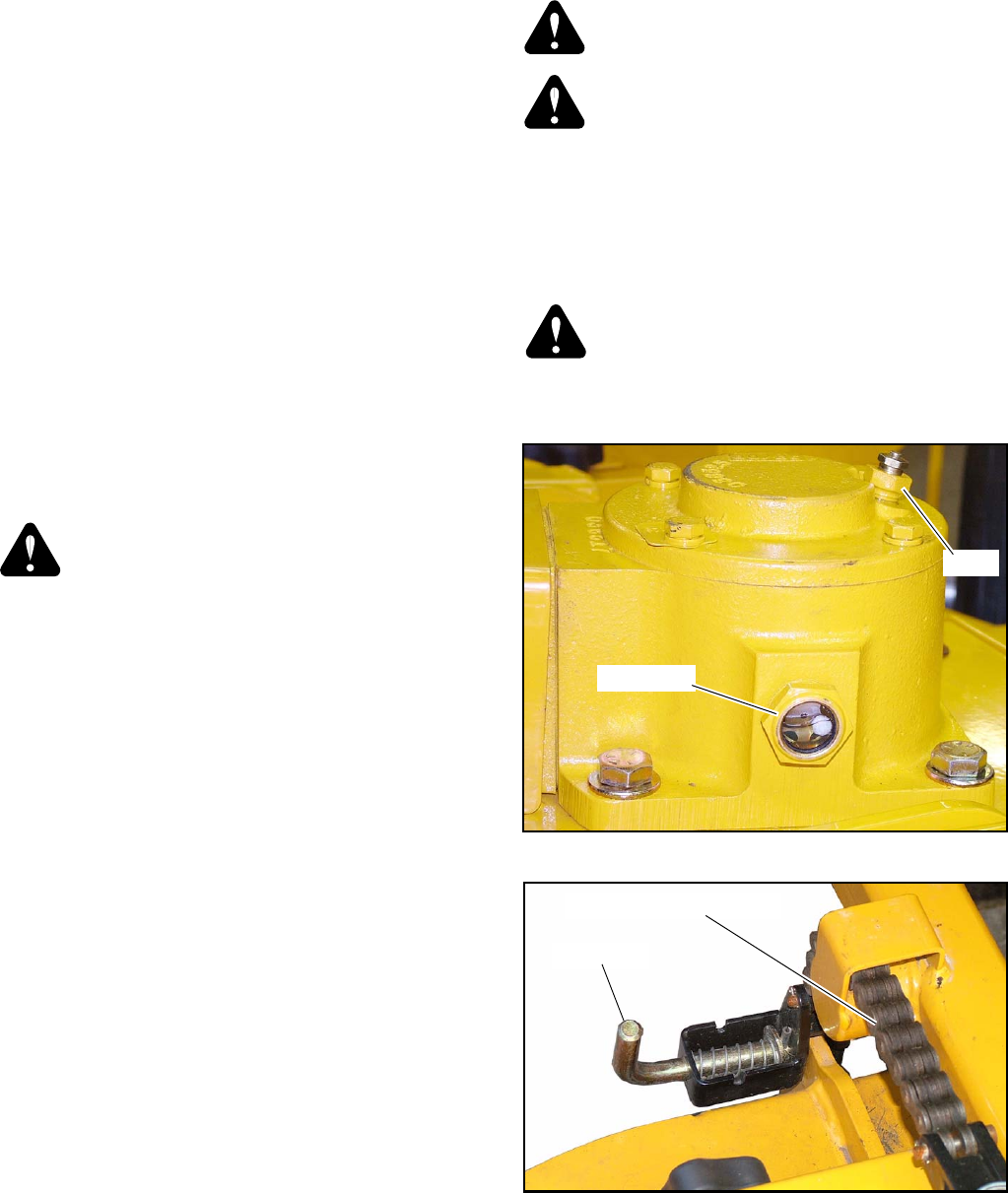
3. Pull out on the locking pins attached to the rear height adjusting chains.
This allows the rear of the mower deck to move freely. Fig. 4-3
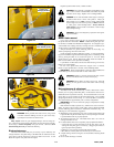
4. Lift the front of the mower deck and pivot it until the holes in the deck
and carrier arms are in alignment. Remove the locking pin from the stor-
age hole and insert it thru the holes in the deck and carrier arm. Fig. 4-4
and 4-5
WARNING: Until the deck is fully pivoted and locked in the
tilted position with the locking pin, it will fall if accidental
movement of the tractor’s tool bar lift control lever occurs.
WARNING: The locking pin must be inserted thru both sides
of the carrier arm to prevent the deck from falling.
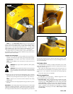
5. Lower the mower deck until the rear anti-scalp roller rests on the ground.
Fig. 4-6
6. When finished working on the underneath side of the deck, reverse the
procedure and lock the deck in the mowing position before operating the
unit.
Cleaning mower deck
DANGER: Before cleaning under mower, make sure the PTO
Control Lever is in the “OFF” position. Raise the mower deck
to highest position and engage parking brake lever. Turn off
engine. Pin deck up in the tilted position using the locking pin.
Lower the mower deck until the rear anti-scalp roller rests on
the ground.
Figure 4-2
Sight gauge
Plug
Figure 4-3
Locking pins
Rear height adjusting chain