


109631_0908 3-3
7. If the measured cutting height is significantly different than the 3.5”
desired height than the front of the deck will have to be adjusted at the
two front gauge wheel forks. The rear of the deck will have to be
adjusted by moving the pins up or down in the adjusting holes. Refer to
Cutting hieght adjustment section for more detailed information.
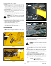
NOTE: Minor leveling can be accomplished by moving the 1/2” cap
screw on either front gauge arm mount forward in the slot, to raise cut-
ting height, or backwards to lower cutting height. Fig. 3-7
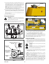
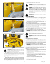
8. If one side of the deck is more than .25” higher than the other side, lower
the high side of the deck by transferring the .25” gauge wheel spacer
from under the gauge wheel fork bearing to the top side. (Fig. 3-8 and 3-
11)
Lower the rear of the deck .25” at the rear height adjustment pin one
hole. Fig. 3-9 and 3-13
9. The mower deck should now be level.
Cutting height adjustment
WARNING: Make sure PTO clutch switch is off, engage trac-
tor parking brake, stop engine, and remove ignition key before
making any adjustments to mower deck.
For best results, make cutting height adjustments on a hard flat surface.
The mower deck can be height adjusted in back as well as in front.
The mower deck has two different cutting height range settings: 2” – 6”
or 1” – 5”. The deck is preset at the factory to the 2” – 6” setting.
Both front and rear height adjustment are in 1/4” increments.
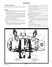
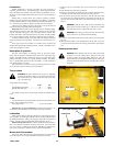
For a quick check of height adjustments: Measure from level surface to
top of mower deck (as indicated in Fig. 3-7) and subtract 5.09 inches. The
balance will be blade height. To be sure mower deck is level, measure at
front and back on both left and right side of deck. Fig. 3-6
To adjust front cutting height
1. Park the unit on a flat surface, set the park brake and using the tractor’s
hydraulic system lift mower deck off the ground. Shut off tractor engine.
Place 8” tall blocks at the four corners of the deck. Restart engine and
lower the deck onto the blocks. Shut off tractor engine and remove key
from the igniton switch.
WARNING: Stop engine. Remove ignition key before getting
off machine.
WARNING: The deck must rest on the blocks to prevent the
deck from being lowered suddenly by the accidental move-
ment of the tractor’s tool bar lift control lever.
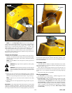
2. Pull up and forward on gauge wheel handle and lift or lower wheel to
desired height (Fig. 3-10). Both gauge wheels should be adjusted to
same height for uniform cutting.
NOTE: To change cutting height range setting to the 1” – 5” range,
reposition the two .5” spacers, located below the gauge wheel bearings, to
above the bearings. Fig. 3-11 & Fig. 3-12
NOTE: 2” – 6” cutting height range: Recesses on side of gauge arm
mounts visually indicate cutting height in 1/2” increments. Each notch
between recesses represents a 1/4” adjustment. When the bottom (lowest)
recess is just visible over top of gauge wheel assembly, cutting height is set
at 6”, when the mower deck is set in the 2” – 6” range (see Fig. 3-7). Next
mark up indicates 5-1/2”, then 5” and so forth. Top mark indicates 2”. Move
gauge wheel assemblies all the way to top of arms for 2” cutting height.
Fig. 3-9
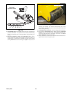
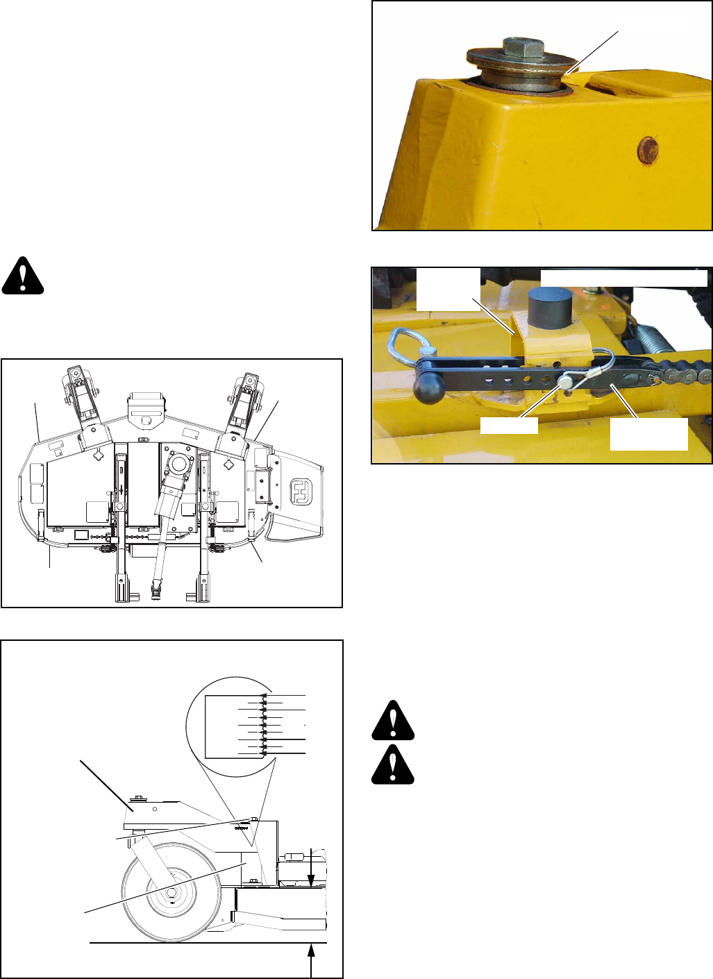
Fig. 3-6
Rear height
adjustment
anchor
Rear height shown set at 2.5”
Rear height
adjusting yoke
Clevis pin
Fig. 3-7
Fig. 3-8
Measure
to top of
deck here
Measure
to top of
deck here
Measure
to top of
deck here
Measure
to top of
deck here
2”
2.5”
3”
4”
5”
6”
3.5”
4.5”
5.5”
Recesses on gauge
arm mount
Gauge wheel
assembly
Measure, then subtract 5.09”
Gauge arm
mount
Loosen cap screw
for adjustments of
less than 1/4”
When mower deck is set in the 2” – 6” range.
.25” Spacer