


3-2 109631_0908
Attaching mower deck to tractor
To attach the Front Mount Mower Deck to a tractor, follow these recom-
mended steps:
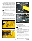
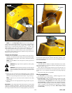
1. Insert the woodruff key into the keyway on the gearbox’s input shaft.
Align the woodruff key with keyway on universal joint of PTO shaft.
Coat the gearbox input shaft with NEVER-SEEZ compound. Slide uni-
versal joint onto gearbox shaft. Secure PTO shaft to gearbox shaft with
5/16” cap screw, flat washer, and 5/16” nut provided. Fig. 3-2 and 3-3
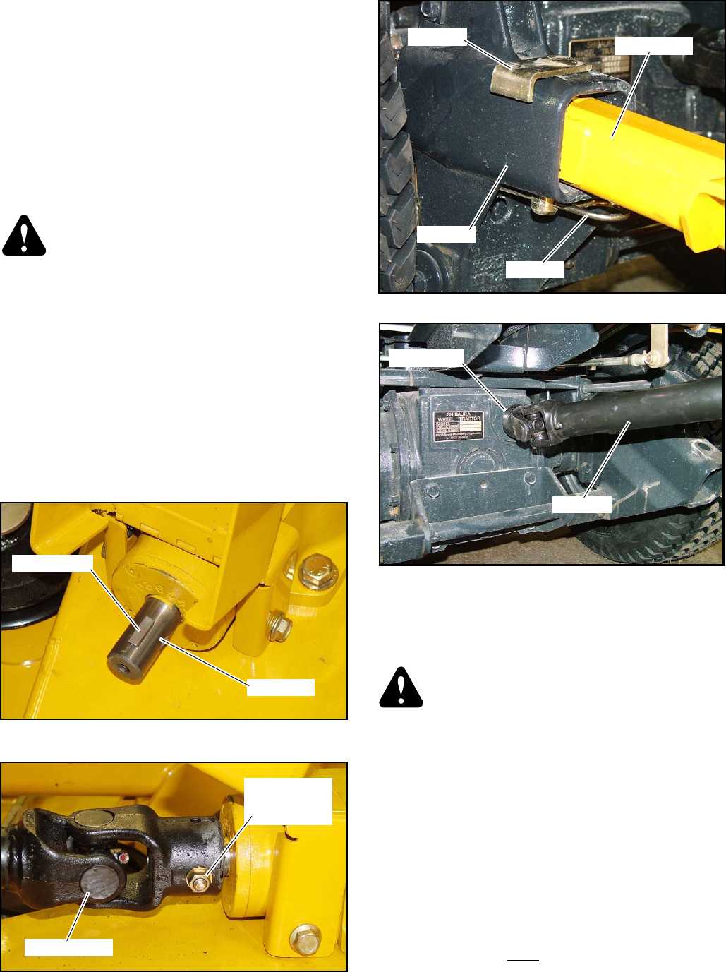
2. Lower tractor tool bar.
3. Block rear of mower deck up so that the deck carrier arms are at the
same height as the tractor tool bar.
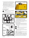
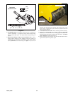
4. Drive the tractor ahead slowly and insert mower deck carrier arms into
the tractor tool bar. Stop tractor engine, engage park brake and remove
key from the igniton switch. Fig. 3-4
WARNING: Stop engine. Make sure PTO switch is off.
Engage park brake and remove ignition key before getting off
machine.
5. By moving the mower deck, align the holes in deck carrier arms and
tractor tool bar.
6. Insert tractor clevis pins through holes in tool bar and carrier arms and
lock clevis pins in place using hair pins provided. Fig. 3-4
7. Attach the PTO shaft to the engine shaft. Fig. 3-5
NOTE: Never attach the PTO shaft to the engine shaft without it being
attached to the mower deck gearbox.
8. The mower deck is now ready for the deck leveling procedure. To
remove deck from tractor, reverse above procedure.
Leveling mower deck
NOTE: Levelness of mower deck when lifted from surface does not
affect levelness of cut in mowing position. Mower deck will mow (cut) level
if it is level when set on level surface.
Refer to tractor owner’s manual for correct tractor tire pressure. To level
mower deck use the following procedure:
1. Park the unit on a flat surface and set the park brake. Shut off tractor
engine and remove key from the igniton switch.
WARNING: Stop engine. Remove ignition key before getting
off machine.
2. Check the deck’s tire pressure and adjust it accordingly. Tire pressure
should be 8-12 psi (55-83 KPa).
3. Set the 3500/3700 tractor’s Tool Bar Lift Control Lever in the fully for-
ward position. (Refer to tractor’s owner’s manual for complete informa-
tion.)
4. Rotate the 3500/3700 tractor’s Weight Control Valve knob counter-
clockwise as far as it will turn to achieve the minimum weight transfer
setting. (Refer to tractor’s owner’s manual for complete information.)
5. Set the deck cutting height to 3.5” at the two front gauge wheel forks and
at the two rear height adjusting linkages.
(Refer to Cutting Height Adjustment section to set cutting height.)
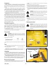
6. Measure from the level surface to the top of the deck. Fig. 3-6
The top of the deck is 5.09” higher than the actual cutting height. Take
the measurements at each of the areas shown (Fig. 3-6) and subtract
5.09” from them. That will give the actual cutting height for that loca-
tion.
Example: 8.59” (top of deck height)
-5.09”
(top of deck to blade distance)
3.50” (cutting height)
NOTE: The rear of the deck should be .2” - .5” higher than the front of
the deck.
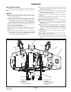
HST foot pedals
Brake pedal
Forward
travel
pedal
Reverse
travel
pedal
Engine shaft
PTO shaft
Fig. 3-2
Fig. 3-3
Input shaft
Woodruff key
Fig. 3-4
Clevis pin
Tool bar
Hair pin
Carrier arm
Universal joint
5/16” cap screw
Flat washer
5-16” nut
Fig. 3-5