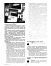
2. Service elements only when restriction indicator shows
red. Check restriction indicator daily or more
frequently if operating in dusty conditions.
3. Loosen wing nut and remove element. Clean the
canister with a damp cloth.
4. Before installing a new element, inspect it by placing a
bright light inside and rotate the element slowly,
looking for any holes or tears in the paper. Also check
gaskets for cuts or tears. Do not attempt to use a
damaged element which will allow abrasive particles
to enter the engine.
5. Reinstall the dust cup. Make sure it seals all the way
around the air cleaner body, then tighten the clamping
thumb screw.
6. Check all fittings and clamps periodically for tightness
and inspect hoses for holes or cracks.
7. Periodically check the intake hose for signs of ingested
dust. Locate and repair the source of ingested dirt.
8. Never operate a machine without an air filter installed.
When operating in extremely dirty conditions, Hustler
recommends Pre-Cleaner Kit, part number 462135, be used
to extend the life of the element. The Pre-Cleaner mounts
on top of the air filter canister and is designed to remove dirt
and debris before it enters the air filter.
Cooling system
Engine cooling is accomplished with circulated water and
Ethylene Glycol mixture. The radiator is equipped with a
pressure cap and recovery tank. System capacity for the
4300 and 4500 tractors is approximately 3.25 U.S. gallon
(12.3 liter). System capacity for the 4200 tractor is
approximately 2.50 U.S. gallon (9.5 liter). System capacity
for the 4400/4420/4600 tractors is approximately 2.75 U.S.
gallon (10.4 liter). A 50-50 mixture is recommended for all
season operation. This mixture provides freeze protection to
-32 degrees F (-35 degrees C). Should temperatures fall
below this level, additional Ethylene Glycol must be added
to the mixture.
Visually inspect the system daily prior to operating
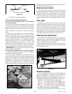
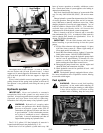
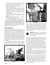
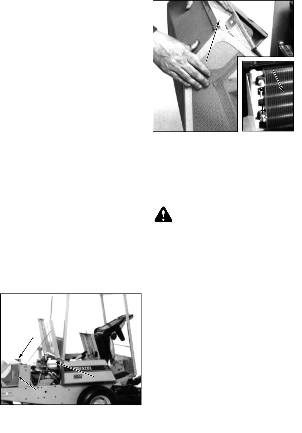
tractor. Check coolant level in the recovery tank located
under the engine hood on the right side, behind fender (Fig.
5-17). The tank is marked with cold engine and hot engine
levels. Level should not go above the hot level mark when
engine is at normal operating temperature, and coolant
should be added to maintain level at or slightly above the
cold level mark at all times. When adding coolant, pre-mix
the solution before adding it to the recovery tank. It is not
necessary to remove radiator cap for adding small amounts
of coolant to system.
DANGER: Never remove radiator cap when
engine is hot. Pressurized hot steam and water
may be released, causing serious burns or
possible blindness.
The system should be drained, flushed and refilled with
fresh solution after every 500 hours of operation. The lower
radiator tank is equipped with a drain cock. Remove the
radiator cap and open this drain for emptying system.
If frequent refilling is necessary or if coolant appears
rusty, thoroughly check the system. Refer to the engine
manual for information on checking and cleaning system.
The engine cooling fan draws air through both the
hydraulic oil cooling and engine cooling radiators. These
are protected by a screen shroud. Keep the shroud clean at
all times and make sure trash is not allowed to accumulate
on or between the radiators, nor allow the fins and cores to
become plugged.
The rear screen is removed by lifting engine hood and
inserting the support rod. Loosen the strap clamps, one on
each side at top, tilt the shroud back, then move the bottom
forward to clear the retaining clips and lift shroud off.
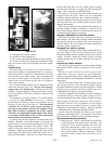
The oil cooler may be separated from its mounting by
loosening the four rubber mounting pad wing nuts and
sliding the cooler assembly back and off the mounts. It
should be noticed that it is not necessary to remove the hex
lock nut, wing nut or rubber spacer to remove or replace the
cooler assembly for servicing or cleaning (Fig. 5-18).
Never force anything into the radiator fins which may
bend or distort them. For cleaning, use compressed air or
pressurized water only.
728444 Rev. 11/02
5-15
Figure 5-17
CCoooollaanntt
RReeccoovveerryy
TTaannkk
Screen Strap
Radiator
Screen
Figure 5-18
WWiinngg NNuuttss
OOiill CCoooolleerr
Radiator Screen Shroud


