


4. Electric PTO clutch switch (Fig. 3-2) – a two-
position switch which controls the electric clutch on
the PTO shaft. Down position is OFF and up position
is ON. When clutch switch is on, the PTO shaft
rotates and delivers live power to attachment requiring
it.
IMPORTANT: Never engage clutch with engine running
at high rpm. Clutch, drive line or attachment could be
damaged.
WARNING: Never turn the PTO switch ON
unless the PTO shaft is securely connected to a
power driven attachment.
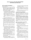
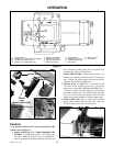
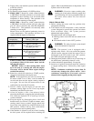
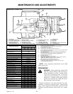
5. Neutral locks (Fig. 3-4) – front and rear locking
devices hold the steering control lever in a neutral
position as tractor will not move when the engine is
running and drive pump is operating. Rotating the
front lock, up and forward, allows the control levers to
be moved forward. Lifting the rear lock with toe of
operator’s foot allows the control lever to be moved in
reverse.
6. Steering control lever (Fig. 3-4) – this lever controls
tractor speed and direction. The lever is used to steer,
accelerate, brake, and change direction.
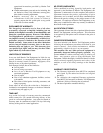
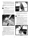
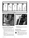
7. Pump clutch lever (Fig. 3-5) – this lever engages and
disengages the hydraulic pump drive belt. Push
forward on lever to engage the hydraulic pump drive.
Pull back on lever to disengage.
IMPORTANT: Always let the engine warm up to
operating temperature and set the throttle at a moderate rpm
before engaging the hydraulic pump clutch. Engage the
clutch slowly. Sometimes more than one attempt is
necessary, particularly when the oil is cold and thickened.
Never snap the clutch to engage. Allow the machine to run
and warm the oil a short time before driving or using
hydraulics.
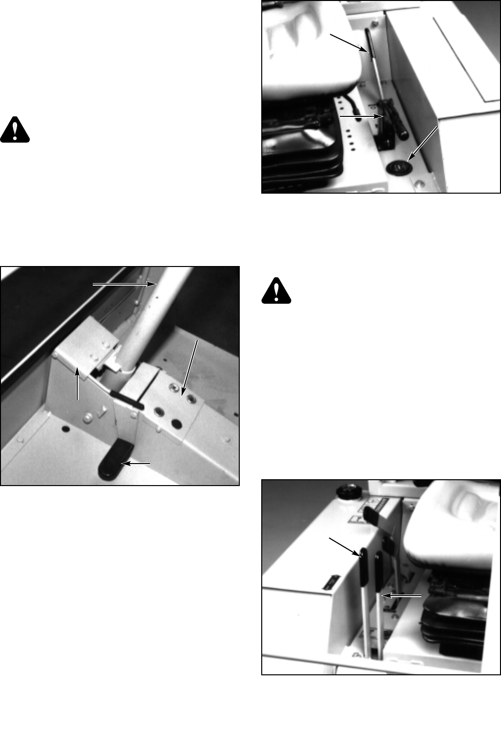
8. Parking brake lever (Fig. 3-5) – engage the parking
brake by rotating the lever up and back until it over-
centers and locks. Release by rotating the lever
forward and down.
WARNING: The parking brake is not designed
to hold tractor on steep slopes.
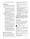
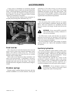
9. Attachment lift lever (Fig. 3-6) – This lever controls
the hydraulic raising and lowering of tractor tool bars
and front end attachments. Pull lever back to raise the
bars and push it forward to lower them.
Normally the attachment is lowered to rest directly
on the ground or gauge wheels and allowed to follow,
or float, over the ground contours (referred to as
“flotation”). For best flotation, push the lever forward
until attachment reaches the ground and hold it for
several seconds until all weight is removed from the
tool bars and lifting cables are slack.
10. Auxiliary control lever (Fig. 3-6) – this lever is for
control of the hydraulic cylinder mounted on some
optional attachments. Use of lever varies with each
728444 Rev. 11/02
3-2
Figure 3-4
IInnssttrruummeenntt
PPaanneell LLiigghhttss
SStteeeerriinngg
CCoonnttrrooll LLeevveerr
Front Neutral
Lock Lever
Rear Neutral
Lock Lever
Figure 3-5
PPaarrkkiinngg
BBrraakkee LLeevveerr
Pump Clutch
Lever
Hour Meter
Figure 3-6
AAttttaacchhmmeenntt
LLiifftt LLeevveerr
AAuuxxiilliiaarryy
CCoonnttrrooll
LLeevveerr