


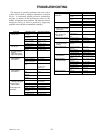


storing and charging specifications.
Common circuit failures are usually caused by shorting,
corroded or dirty terminals; loose connections, defective
wire insulation or broken wires. Switches, solenoids and
ignition components may also fail, causing a shorted or open
circuit.
Before attempting any failure diagnosis of the electrical
system, use a test light or voltmeter to check the battery
voltage. If the battery voltage is satisfactory, check the
cleanliness and tightness of the terminals and ground
connections. A general understanding of electrical servicing
and use of basic test equipment is necessary for
troubleshooting and repair.
Major overhaul or repair of the starting motor or alternator
should be performed by trained technicians only.
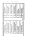
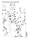
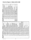
Although integral, the tractor electrical system can be
described as three separate circuits for explanation and
troubleshooting.
1. Run Circuit: this circuit supplies needed continuity
for normal operation of engine, controls and electric
clutch while the operator remains seated on the tractor.
For personal protection, the engine will stop should the
operator become unseated while operating the tractor,
when the neutral lock is disengaged or the electric
clutch is switched ON.
When the ignition switch is turned to the RUN
position, battery voltage is supplied from the switch to
the operator’s seat switch. When weight is applied to
the seat, the normally open seat switch closes and
completes the circuit through the relay coil to ground.
Current flowing through the relay coil closes the
normally open relay switch, which completes the
circuit to the neutral lock switch and fuel shut-off
solenoid.
So long as appropriate weight remains on the seat,
the engine will run when the electric clutch switch is
ON and/or the neutral lock is disengaged. However,
when weight is removed from the seat, the engine fuel
shut-off solenoid will close and the engine will stop.
2. Starting Circuit: this circuit supplies electrical power
for engine starting, providing the interlock is engaged
and electric clutch is switched OFF. The operator seat
switch is bypassed in this mode.
When the ignition switch is turned to the START
position, battery voltage is available from the switch to
the electric clutch switch. When the electric clutch
switch is in the OFF position, current passes through
the center switch tap to the normally open neutral lock
switch. When the neutral lock is engaged, the switch
is closed and current flows through one switch circuit
to the starter for engine cranking.
Current from the ignition switch passes through the
electric clutch switch, when it remains in the OFF
position, to and through the other neutral lock switch
circuit and on to the fuel shut-off solenoid and coil.
In summary, this is a safety control circuit which
inhibits the supply of heavy current to the starter
motor, unless the electric clutch switch is in the OFF
position and the neutral lock is engaged.
3. Accessory and Instrument Circuit: this circuit is
used for the warning lights and audible signal
connected to the engine oil, alternator and water
sensing units. It also supplies power for the hour
meter and electric clutch switch.
When the ignition switch is turned to the RUN
position, battery voltage is supplied to the engine alert
system via ignition switch terminals. Grounding, to
complete the circuit and signal the operator, is through
the oil pressure and water temperature sending units.
The alternator warning light is connected between
the ignition switch and the alternator field circuit.
The ignition switch also supplies battery voltage
through the on-off toggle switch and in-line 5 amp fuse
to the electric clutch with frame ground wire. The
hour meter operates from a wire tap at electric clutch
switch and a frame ground wire.
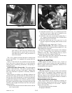
Burnishing the electric clutch
WARNING: To insure maximum performance
and life, it is necessary to burnish the clutch.
The electric clutch will need to be burnished properly if a
new clutch is installed. Burnishing the clutch develops
maximum contact between the clutch armature and the rotor.
To burnish the clutch use the following procedure:
1. Attach an implement to the tractor PTO shaft per the
implement’s mounting instructions.
2. Cycle the clutch on and off 50 times (15 seconds on
and 15 seconds off) with the engine operating at low
idle, approximately 1500 rpm. Make certain that the
PTO shaft comes to a complete stop between cycles.
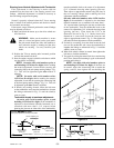
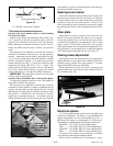
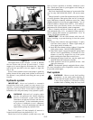
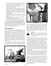
Access to engine and hydraulic
pumps
WARNING: Always wear adequate eye
protection when servicing the hydraulic system,
battery and cooling system.
728444 Rev. 11/02
5-11
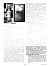
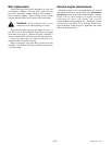
Figure 5-9
BBaatttteerryy
LLooccaattiioonn
LLeefftt ffeennddeerr