


ASSEMBLY
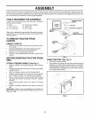
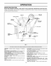
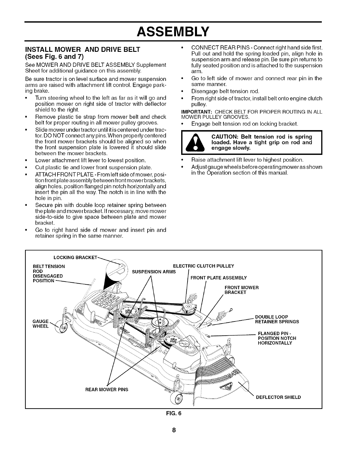
INSTALL MOWER AND DRIVE BELT
(Sees Fig. 6 and 7)
See MOWER AND DRIVE BELT ASSEMBLY Supplement
Sheet for additional guidance on this assembly.
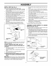
Be sure tractor is on level surface and mower suspension
arms are raised with attachment lift control, Engage park-
ing brake,
• Turn steering wheel to the left as far as it will go and
position mower on right side of tractor with deflector
shield to the right.
• Remove plastic tie strap from mower belt and check
belt for proper routing in all mower pulley grooves.
• Slide mower under tractor until itiscentered under trac-
tor, DO NOT connect any pins.When properly centered
the front mower brackets should be aligned so when
the front suspension plate is lowered it should slide
between the mower brackets,
• Lower attachment lift lever to lowest position,
• Cut plastic tie and lower front suspension plate,
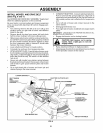
• ATTACH FRONT PLATE - From left sideof mower, posi-
tion front plate assembly between front mower brackets,
align holes, position flanged pin notch horizontally and
insert the pin all the way. The notch is in line with the
hole in pin.
• Secure pin with double loop retainer spring between
the plate and mower bracket, If necessary, move mower
side-to-side to give space between plate and mower
bracket,
• Go to right hand side of mower and insert pin and
retainer spring in the same manner.
• CONNECT REAR PINS -Connect right hand side first.
Pull out and hold the spring loaded pin, align hole in
suspension arm and release pin, Be sure pin returns to
fully seated position and isattached to the suspension
arm.
• Go to left side of mower and connect rear pin in the
same manner,
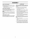
• Disengage belt tension rod,
• From right side of tractor, install belt onto engine clutch
pulley,
IMPORTANT: CHECKBELTFOR PROPER ROUTINGIN ALL
MOWERPULLEYGROOVES.
• Engage belt tension rod on locking bracket,
I& CAUTION: Belt tension rod is spring
loaded. Have a tight grip on rod and
engage slowly.
• Raise attachment lift lever to highest position.
• Adjust gauge wheels before operating mower as shown
in the Operation section of this manual,
LOCKING
BELTTENSION
ROD
DISENGAGED
WHEEL
l
REAR MOWER PINS
ELECTRIC CLUTCH PULLEY
SUSPENSION ARMS
FRONT PLATE ASSEMBLY
! j/FRONT MOWER
BRACKET
J_
DOUBLELOOP
RETA,NERSPR,NGS
FLANGED PIN -
POSITION NOTCH
HORIZONTALLY
DEFLECTOR SHIELD
FIG. 6
8