


SERVICE AND ADJUSTMENTS
&
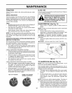
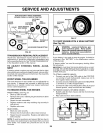
WARNING: TO AVOID SERIOUS INJURY, BEFORE PERFORMING ANY SERVICE OR ADJUSTMENTS:
Depress clutch/brake pedal fully and set parking brake.
Place gearshift lever in neutral (N) position.
• Place attachment clutch in "DISENGAGED" position.
• Turn ignition key to "STOP"and remove key.
• Make sure the blades and all moving parts have completely stopped.
• Disconnect spark plug wire from spark plug and place wire where it cannot come in contact
with plug.
TRACTOR
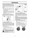
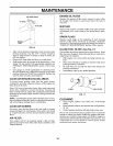
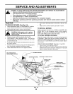
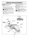
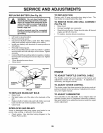
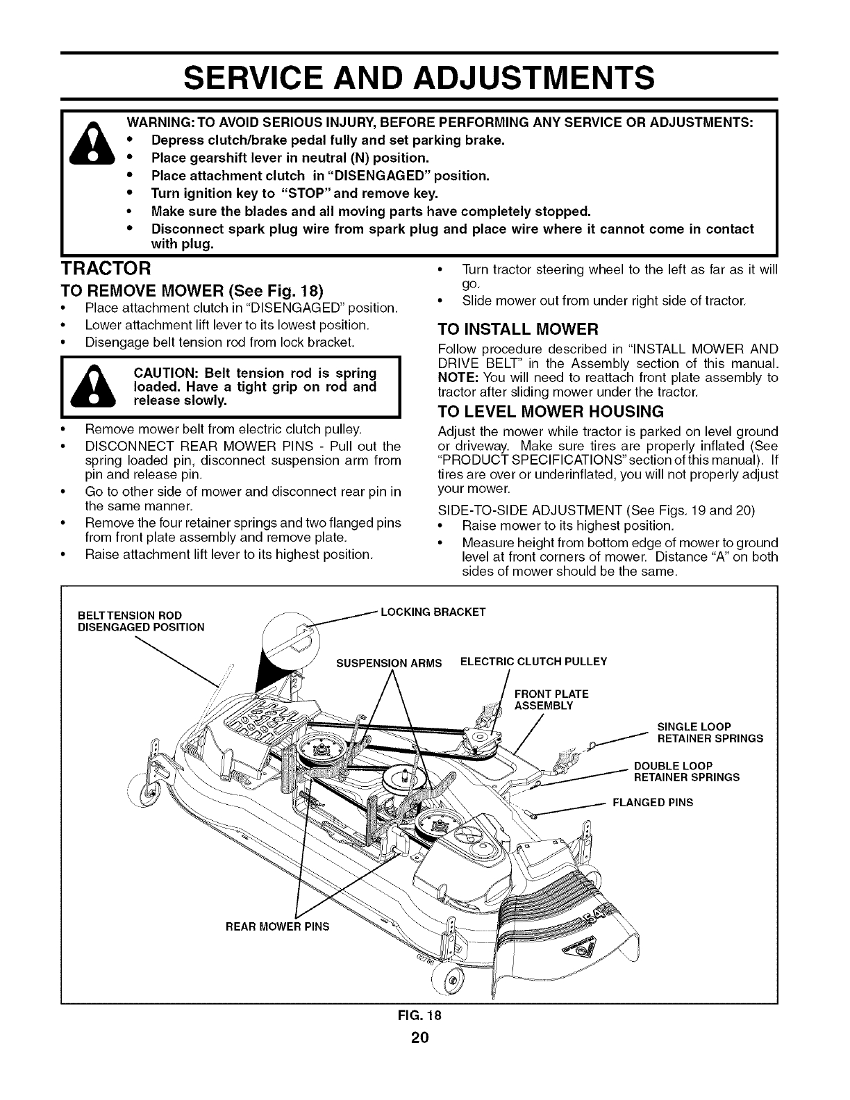
TO REMOVE MOWER (See Fig. 18)
• Place attachment clutch in "DISENGAGED" position,
• Lower attachment lift lever to its lowest position,
• Disengage belt tension rod from lock bracket,
J& CAUTION: Belt tension rod is spring J
loaded. Have a tight grip on rod and
I
release slowly.
• Remove mower belt from electric clutch pulley,
• DISCONNECT REAR MOWER PINS - Pull out the
spring loaded pin, disconnect suspension arm from
pin and release pin.
• Go to other side of mower and disconnect rear pin in
the same manner.
• Remove the four retainer springs and two flanged pins
from front plate assembly and remove plate,
• Raise attachment lift lever to its highest position,
• Turn tractor steering wheel to the left as far as it will
go,
• Slide mower out from under right side of tractor,
TO INSTALL MOWER
Follow procedure described in "INSTALL MOWER AND
DRIVE BELT" in the Assembly section of this manual.
NOTE: You will need to reattach front plate assembly to
tractor after sliding mower under the tractor.
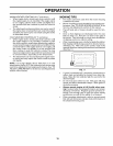
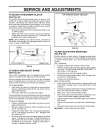
TO LEVEL MOWER HOUSING
Adjust the mower while tractor is parked on level ground
or driveway, Make sure tires are properly inflated (See
"PRODUCT SPECIFICATIONS" section of this manual), If
tires are over or underinflated, you will not properly adjust
your mower.
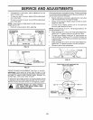
SIDE-TO-SIDE ADJUSTMENT (See Figs. 19 and 20)
• Raise mower to its highest position.
• Measure height from bottom edge of mower to ground
level at front corners of mower. Distance "A" on both
sides of mower should be the same.
BELTTENSION ROD
DISENGAGED POSITION
LOCKING BRACKET
SUSPENSION ARMS
ELECTRIC CLUTCH PULLEY
FRONT PLATE
ASSEMBLY
SINGLE LOOP
.f RETAINER SPRINGS
DOUBLELOOP
RETAINER SPRINGS
FLANGED PINS
REAR MOWER PINS
FIG. 18
20