


SERVICE AND ADJUSTMENTS
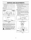
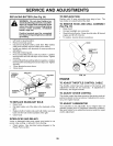
• If adjustment is necessary, make adjustment on one
side of mower only.
• To raise one side of mower, tighten lift link adjustment
nut on that side,
• To lower one side of mower, loosen lift link adjustment
nut on that side,
NOTE: Each full turn of adjustment nut will change mower
height about 3/16".
• Recheck measurements after adjusting,
BOTTOM EDGE BOTTOM EDGE
OF MOWER TO OF MOWER TO
GROUND V 7 D
FIG. 19
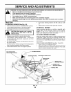
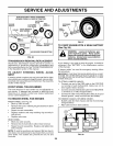
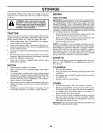
Check adjustment on right side oftractor. Position any blade
sothe tip is pointing straight forward, Measure distance "B"
at front and rear tip of the blade.
• Before making any necessary adjustments, check that
both front plate links are equal in length.
• If links are not equal in length, adjust one link to same
length as other link.
• To lower front of blade, loosen nut "C" on both front
links an equal number of turns.
NOTE: Each full turn of nut "C" will change distance, "B"
by approximately 3/16",
• Whendistance"B"isl/8"tol/2"loweratfrontthanrear,
tighten nut "D" against trunnion on both front links,
• To raise front of blade, loosen nut "D" from trunnion on
both front links. Tighten nut "C" on both front links an
equal number of turns. The two front links must remain
equal in length.
• Whendistance"B"is 1/8" to 1/2" lower at frontthan rear,
tighten nut "D" against trunnion on both front links.
• Recheck side-to-side adjustment,
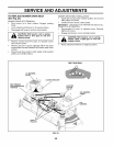
_ SUSPENSION
_\ARM
__ _o_\-2 _-- -- 27_
r!_ ....... \ \\ LIFT LINK
eL9 ........._-_-_ --. ADJUSTMENT
NUT
FIG. 20
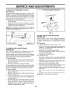
FRONT-TO-BACK ADJUSTMENT (See Figs. 21 and 22)
IMPORTANT: DECK MUST BE LEVEL SIDE-TO-SIDE. IFTHE
FOLLOWING FRONT-TO-BACK ADJUSTMENT IS NECESSARY,
BE SURE TO ADJUST BOTH FRONT LINKS EQUALLY SO
MOWER WILL STAY LEVEL SIDE-TO-SIDE.
To obtain the best cutting results, the mower blades should
be adjusted so thefront tip isapproximately 1/8" to 1/2" lower
than the rear tip when the mower is in its highest position,
& CAUTION: Blades are sharp. Protect
your hands with gloves and/or wrap
blade with heavy cloth.
'B .... B'_
FIG. 21
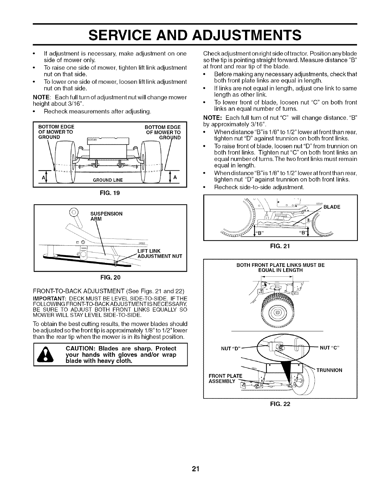
BOTH FRONT PLATE LINKS MUST BE
EQUAL IN LENGTH
NUT "D"-_
FRONT PLATE'_,.
ASSEMBLY
NUT "C"
_ TRUNNION
FIG. 22
21