


50 – English
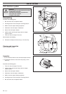
CRANKSHAFT, PISTON AND CYLINDER
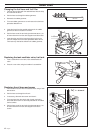
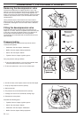
3. Pull off the hose to the impulse channel and seal the nipple.
4. Pump up the pressure to 80 kPa (0.8 bar).
5. Wait 30 seconds.
6. The pressure must not fall below 60 kPa (0.6 bar).
7. Leakage can occur on the crankshaft’s sealing rings.
8. Dismantle the cover plates.
Assemble the following parts:
• Flywheel. See the chapter "Ignition system".
• Starter. See the chapter "Starter".
• Carburettor. See the chapter "Carburettor".
• Muffler. See the chapter "Safety equipment".
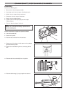
Pressure testing
The following parts must be removed to pressure test the
crankcase and cylinder:
• Carburettor. See the chapter "Carburettor".
• Muffler. See the chapter "Safety equipment".
• Starter. See the chapter "Starter".
• Flywheel. See the chapter "Ignition system".
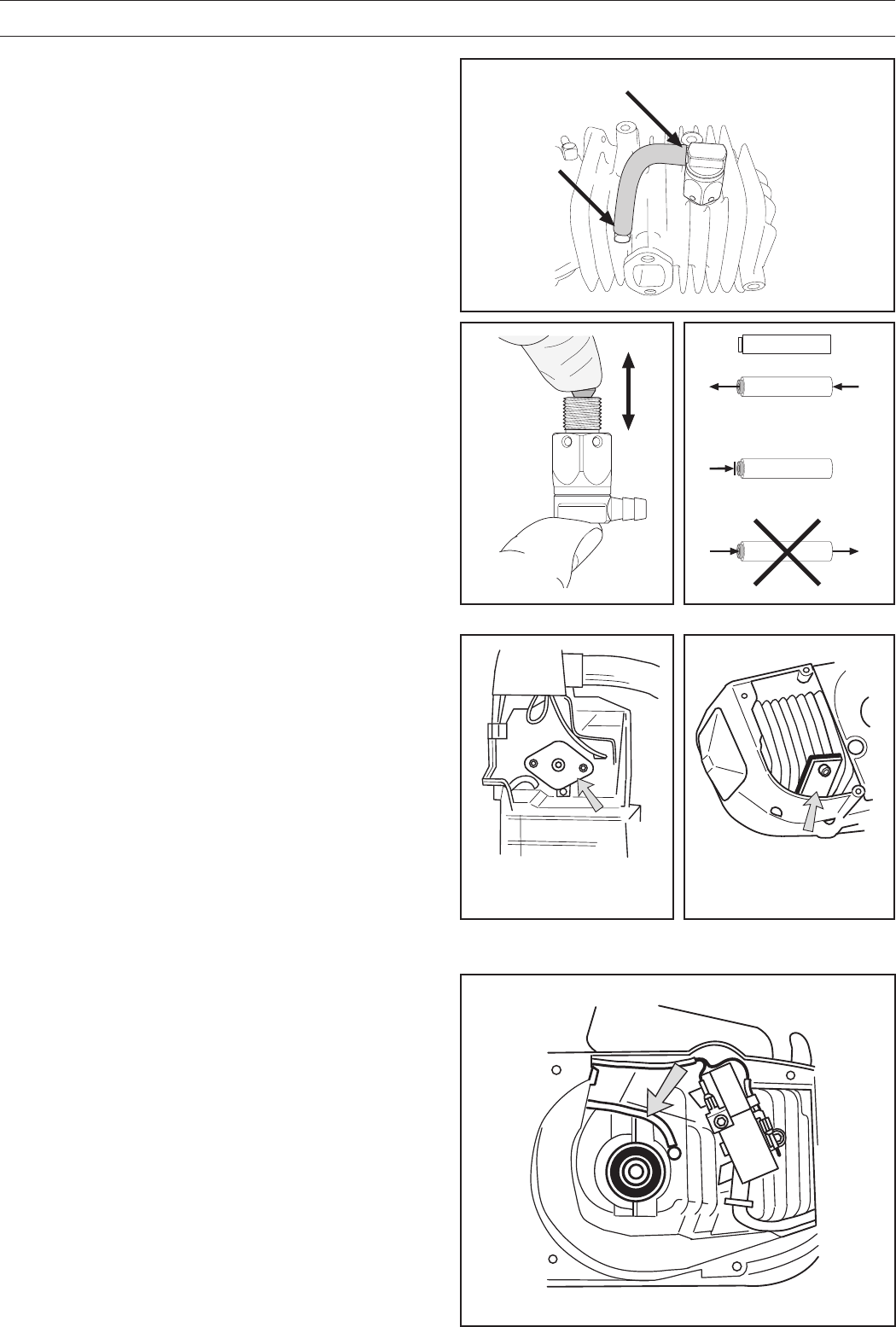
Carry out pressure testing as follows:
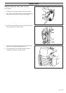
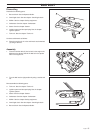
1. Fit the cover plate 502 52 01-01 on the inlet manifold. Now
connect tool 502 50 38-01 to the cover plate.
2. Fit the cover plate 502 71 39-01 on the exhaust port.
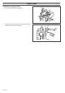
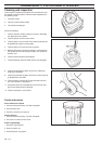
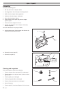
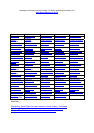
Removing the decompression valve
Disconnect the pipe from the nipples (B and C). Use a ring
spanner (15 mm) to remove the valve from the cylinder. Check
that the valve can be pressed in easily and springs back out
again. If the valve is stiff it should be soaked in petrol for a while
to loosen the particles of soot. It can then be blown clean with
compressed air.
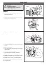
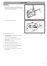
Use a pressure tester to check that the non-return valve is
working correctly. Air should only pass through in the direction
of the arrow, see diagram. If the non-return valve is defective,
replace it.
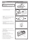
Fitting the decompression valve
Screw the valve into the cylinder using a ring spanner to a
torque of 12–14 Nm. Then use a spanner to turn the brass part
of the valve to roughly the position shown in the diagram, so
that the pipe can be connected in the correct position.
The brass part is not threaded and can therefore be turned in
either direction.
B
C
OK
OK