


English – 49
CRANKSHAFT, PISTON AND CYLINDER
Assembly
Assembly of the piston and cylinder is carried out as follows:
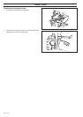
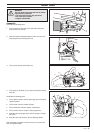
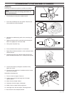
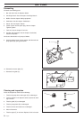
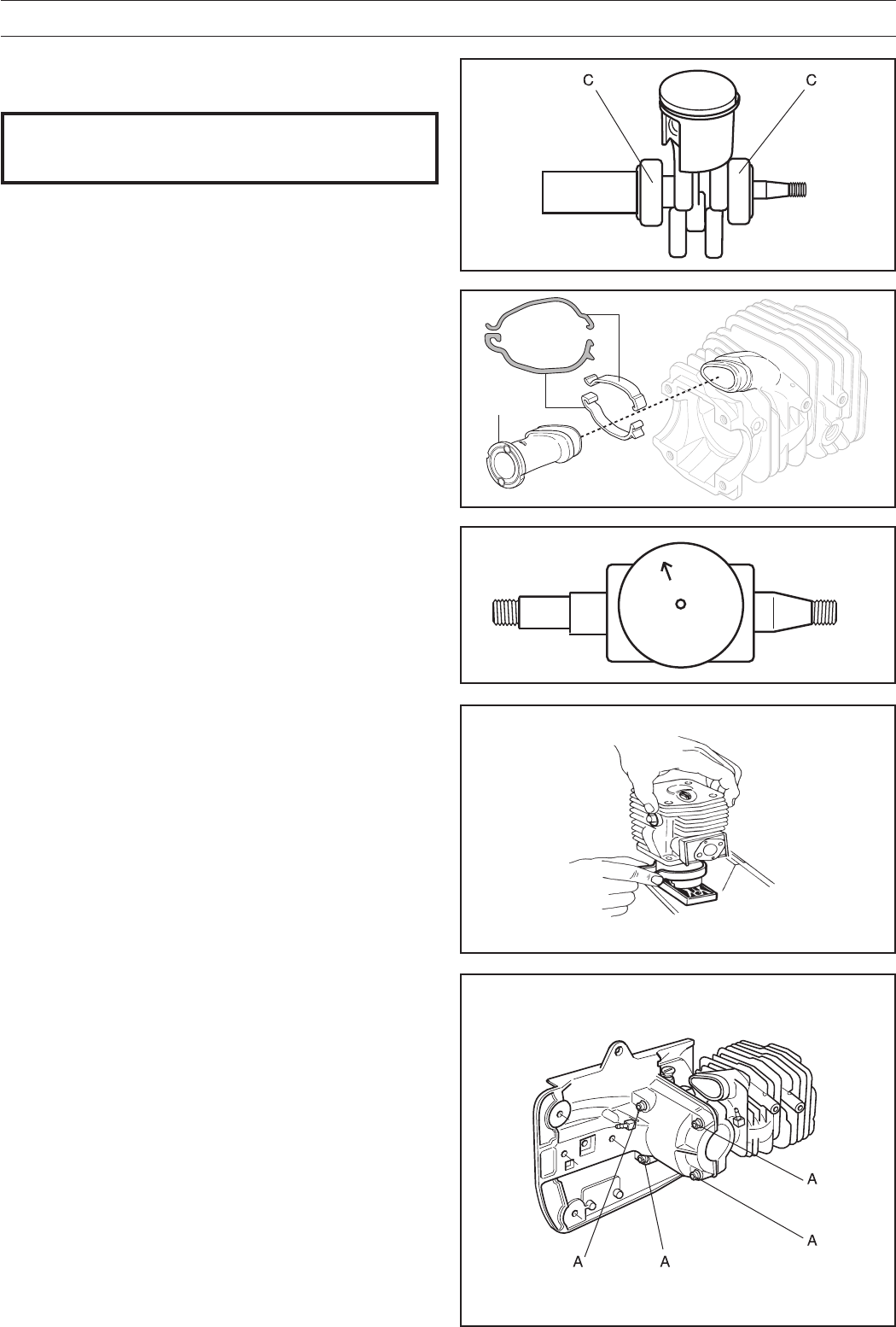
9. Insert the four bolts (A) and tighten crosswise. Finally
tighten to 8-10 Nm.
10. Pressure test the crankcase in accordance with the instruc-
tions on the next page.
Assemble the following parts:
11. Tank unit. See the chapter "Tank unit".
12. Ignition system and the spark plug. See the chapter
"Ignition system".
13. Starter. See the chapter "Starter".
14. Carburettor. See the chapter "Carburettor".
15. Muffler. See the chapter "Safety equipment".
16. Centrifugal clutch. See the chapter "Centrifugal clutch".
17. Bar and chain. See the Operator Guide.
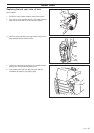
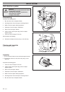
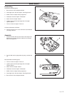
6. Fit the crankshaft with the piston in the crankcase.
7. Apply silicone rubber 504 98 26-01 to the crankcase halves'
contact surfaces.
8. Compress the piston ring, either by hand or by using the
piston assembly tool 502 50 70-01. Carefully fit the cylinder.
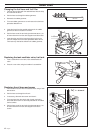
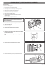
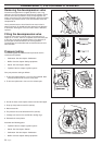
3. Lubricate the needle bearing and fit in the connecting rod
little-end.
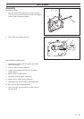
4. Replace the piston with the arrow facing the exhaust port.
Slide in the gudgeon pin and fit the circlip.
5. Oil the piston and piston ring.
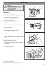
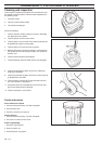
2. Fit the inlet manifold (B) from the cylinder. Check that the
inlet manifold is turned as illustrated.
NOTE!
Exercise care so that dirt and foreign particles do not
enter dismantled parts.
1. Fit the bearing (C) using the a suitable mandrel.
B