


English – 37
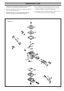
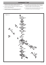
CARBURETTOR
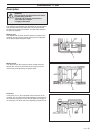
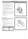
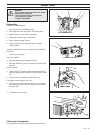
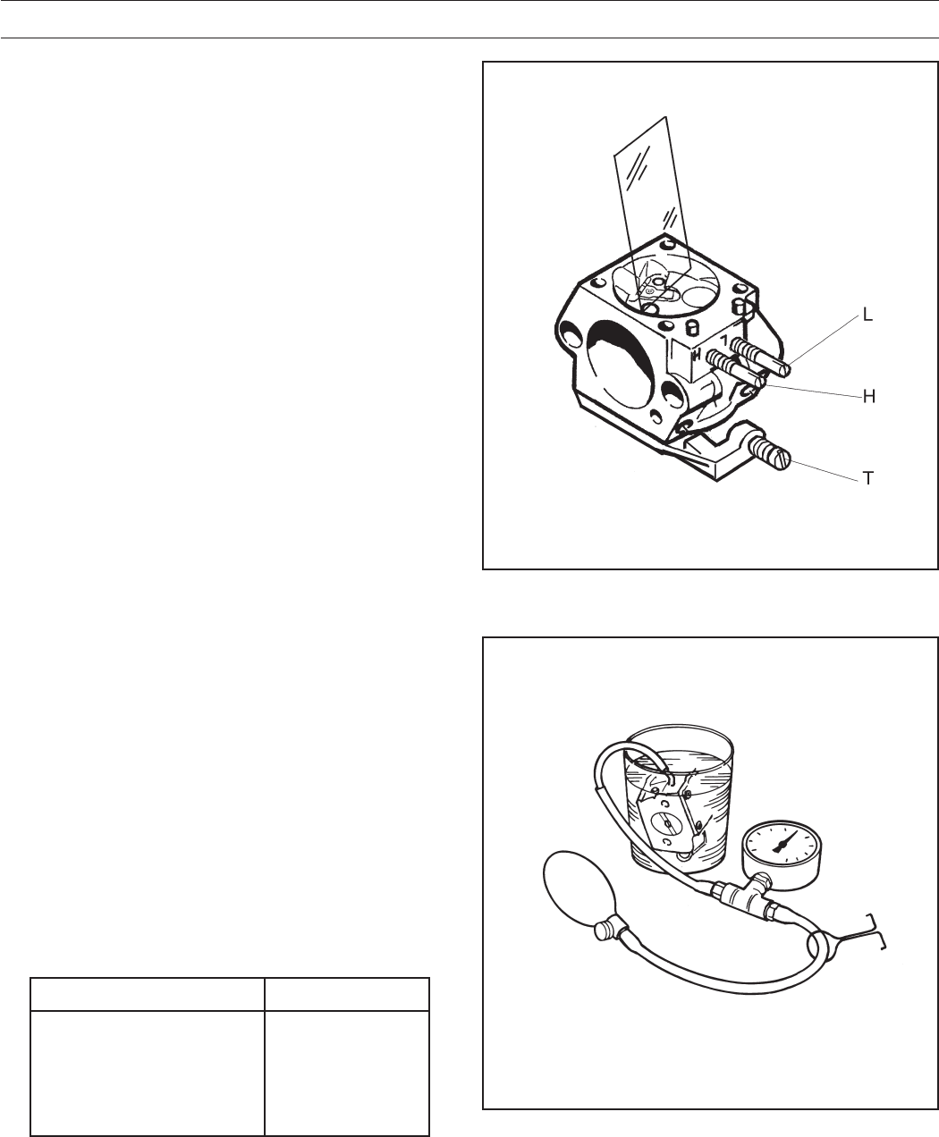
5. Fit the high speed needle (H) as follows:
A. Screw in the new H-needle clockwise until it bottoms.
Then anticlockwise 3 1/2 turns.
B. Press a new locking cap onto the H-needle to the first
stop, i.e. the locking cap should not be fixed.
6. Fit the low speed needle (L) as follows:
A. Screw in the new L-needle clockwise until it bottoms.
Then anticlockwise 1 3/4 turns.
B. Press a new locking cap onto the L-needle to the first
stop, i.e. the locking cap should not be fixed.
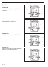
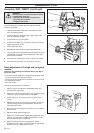
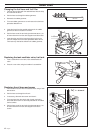
7. Fit the pump diaphragm (M), gasket (K) and cover (J) on
the pump unit.
8. Fit the needle valve (P) with lever arm (E), shaft and spring
as well as fitting the bolt (D).
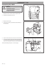
9. Check using a ruler or the like that the lever arm (E) is level
with the heels next to the lever arm. The lever arm can be
bent if necessary.
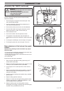
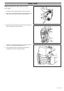
10. Fit the control diaphragm (B) with packing and cover (A) on
the metering unit.
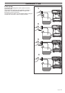
11. Carry out a pressure test.
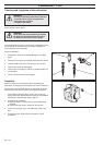
Pressure testing
Pressure testing should be carried out with the carburettor fully
assembled. Testing should always be carried out after the
carburettor has been repaired, but a test can also be made for
trouble shooting before dismantling.
Test the carburettor as follows:
1. Connect pressure tester 502 50 38-01 to the carburettor’s
fuel intake.
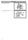
2. Lower the carburettor into a beaker of water.
3. Pump up the pressure to 50 kPa (0.5 bar) and squeeze
together the pump tube.
4. No leakage is permitted. If a leakage occurs refer to the
table below.
Leakage on Fault with
Diffuser jets Needle valve
Leakage in the impulse pipe Pump diaphragm
Ventilation hole above Control diaphragm
the metering unit