


13
ASSEMBLY
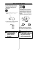
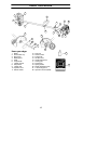
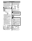
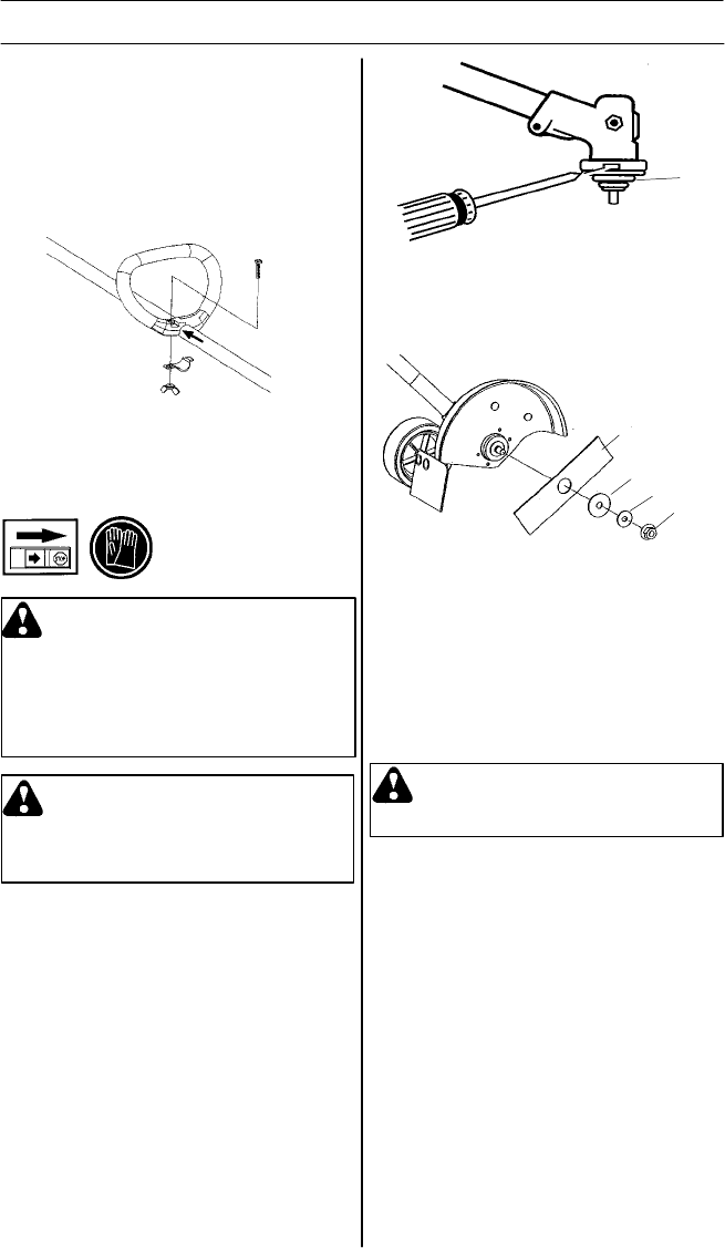
3. While holding the screwdriver in position,
remove locking nut by turning clockwise.
4 . Remove both washers (C and D) and
the blade (B) from the output shaft.
5. Install blade onto output shaft.
6. Reinstall both washers and locking nut
(counterclockwise).
7 . Tighten locking nut firmly with a wrench
while holding screwdriver in position.
8. Remove the screwdriver.
9. Turn blade by hand. If the blade binds
against the shield, or appears to be un-
even, the blade is not centered, a nd
you must reinstall.
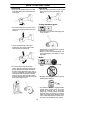
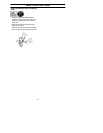
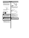
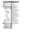
Assembling the blade
1. Align hole in the dust cup with the hole in
the side of the bevel gear by rotating the
dust cup (A).
2. Insert a small screwdriver into aligned
holes. This will keep the o utput shaft from
turning whil e loosening the lo cking nut (E).
N
O
TE: Make sure u nit is assembled cor-
rectly as shown in this manual.
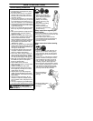
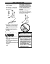
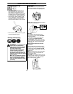
Assembling the loop handle
S Position the handle on the shaft. Note
that the handle m ust be m ounted be-
tween the two arrows on the shaft.
S Fit the screw, securing plate and wing
nut as shown in the diagram.
S Tighten the wing nut.
B
D
C
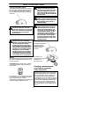
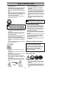
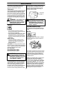
WARNING: The blade will contin-
ue to spin after the engine stops or
after the throttle trigge r has been re-
leased. To avoid serious injury ,
make s ure the blade has stopped
coasting and disconnect the spark
plug before performing work on the
blade.
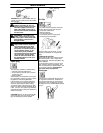
WARNING: Wear protective
gloves when handli ng or performing
mainten ance on the blade to avoid
injury. The blad e is sharp and can
cut you even when it is not moving.
A
E
WARNING: Under no circum-
stances should the edger be used
without the blade guard installed.