


English – 65
ELECTRICAL SYSTEM
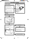
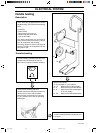
Handle heating
Some saws are equipped with an electric
handle heating. This consists of the following
parts:
• Generator.
• Power switch.
• Heater loop in the tank unit.
• Handle loop with heater loop.
(One or two loops).
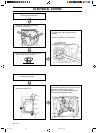
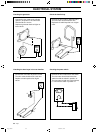
Description
The above components are connected in
series, which means that if there is a fault in
one, all components stop working.
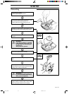
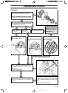
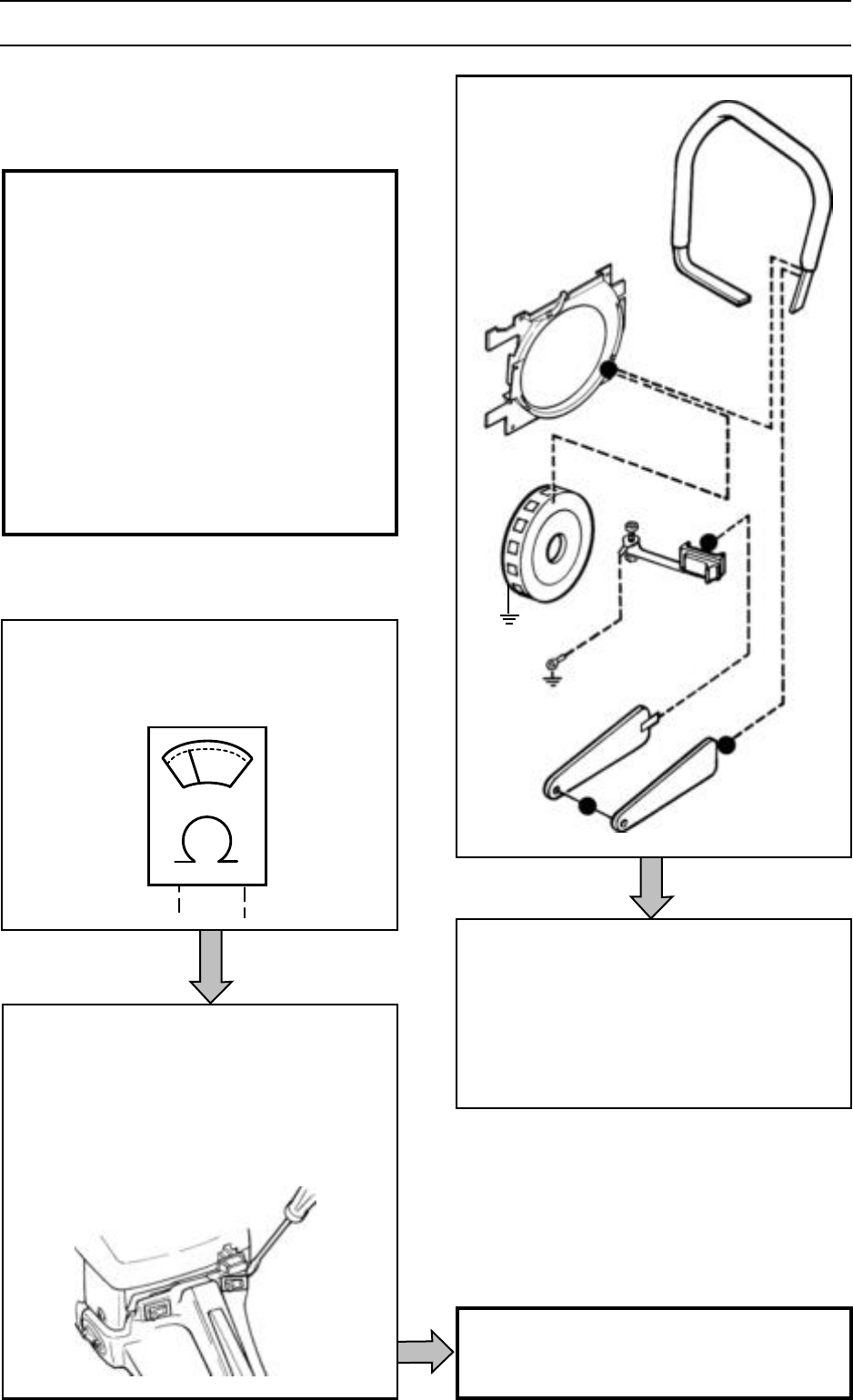
The wiring diagram is shown in the figure to
the right. The order of components can vary
from saw to saw.
A1
B
C
D
E
A2
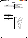
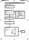
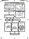
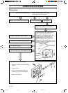
Trouble shooting can take place with most
components connected to the saw. An
ohm meter is required for trouble shooting.
Before trouble shooting individual
components remove the power switch and
disconnect one of the switch's cables.
Remove other components as necessary.
E.g. the cylinder cover. See the operating
instructions.
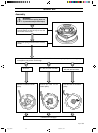
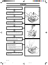
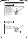
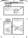
Trouble shooting individual components, see
next page.
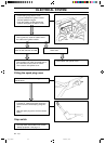
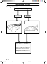
Measurement points:
A1 and A2 Earth. E.g. the cylinder
A1 - B Measurement of the generator
B - C Measurement of the handle loop
C - D Measurement of the heater loops
in the rear handle
D - A2 Measurement of the power switch
Trouble shooting
Eng, p 40-82 96-09-13, 10.2365