


114 – English
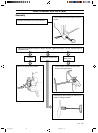
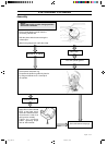
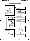
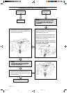
CRANKCASE AND CRANKSHAFT
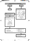
Before the crankcase can be split the follow-
ing must be removed:
A. Chain and bar.
See operating instructions.
B. Starter. See page 57.
C. Electrical system. See page 61.
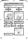
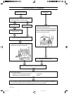
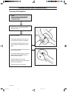
NOTE!
Ensure that no dirt or foreign particles
enter the bearings.
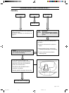
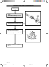
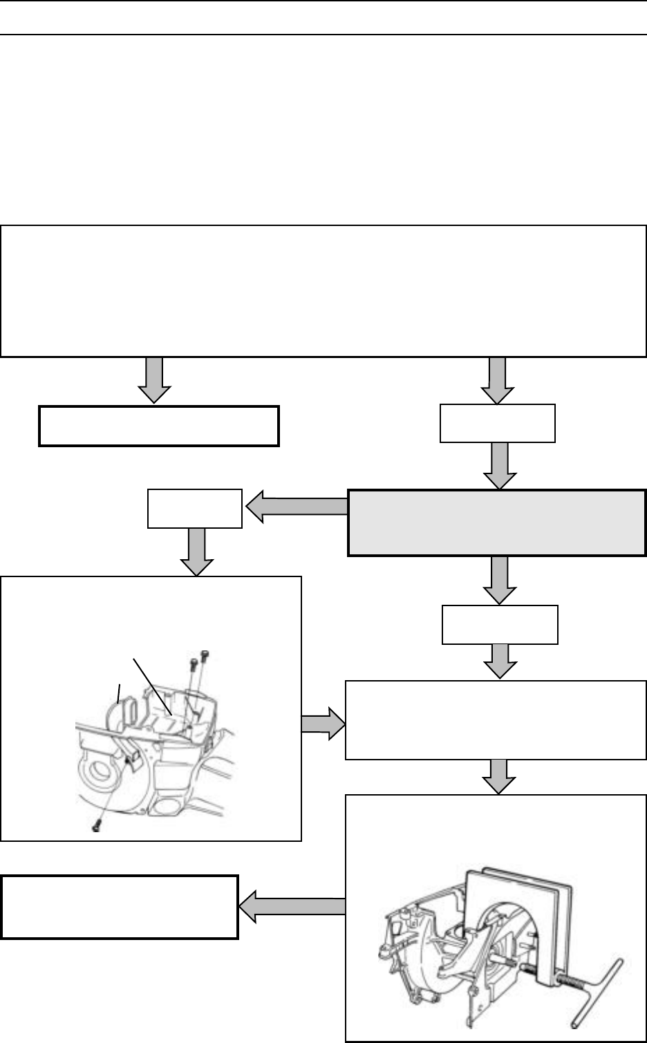
On saw 394, remove the carburettor
chamber floor (A) and air jet (B).
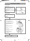
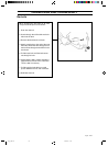
Undo the bolts holding the crankcase to-
gether. The bolts are on the clutch side.
Note the location of the bolts that are of a
different length.
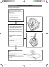
Split the crankcase using tool
502 51 61-01.
D. Centrifugal clutch. See page 67.
E. Oil pump. See page 70.
F. Carburettor.
G. Muffler. See page 49.
H. Piston and cylinder. See page 108.
I. Tank unit. See page 103.
Saw 394.
Other saws.
Other saws
Saws 36, 40, 41 and 45. See next page.
See continuation on next page.
A
B
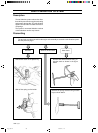
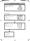
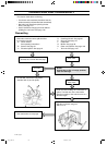
This section deals with the following:
• Crankcase and crankshaft (describes how the
whole assembly is dismantled and assembled).
• Bar bolts (only describes replacing the bar
bolts). See page 121.
• Seals. Describes changing the seals without
splitting the crankcase. See page 122.
Dismantling
Eng, p 83-124 96-09-13, 13.02114