


2 Operation continued
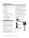
C Response Test
CAUTION
DO NOT BLOCK INLET
OR OUTLIET PORTS
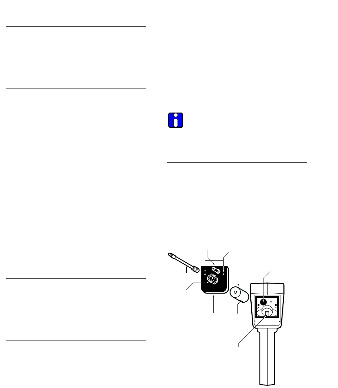
INLET
OUTLET
TEST UNIT PRIOR TO USE
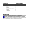
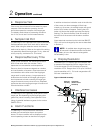
Sensor
(SMART-CELL)
Filter Material
Sensor
alignment
pin
Sensor
alignment
groove
Manifold lid
Inlet fitting
Sampling
wand
Outlet tube
barb fitting
Thumbscrews
(loosen to remove
manifold lid)
Figure 3: Manifold Assembly
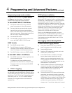
Prior to use, the unit should first be tested for proper
response. With the detector operating, the unit
should be exposed to a sample of the target gas.
The display should show an increasing concentra-
tion. If not, do not use it for field measurements.
D Sample Inlet Port
The Manning EC-P2 is provided with a quick disconnect
flexible extension wand. It will work with or without the
wand. When using the extension wand, the internal
walls must be kept dry. Water on the walls of the tubing
can potentially absorb the target gas. To dry, allow the
unit to pump dry, ambient air for 15 minutes.
E Response/Recovery Time
Under normal conditions, the instrument will reach
90% of final value within two minutes. This is
dependent on concentration and temperature.
Recovery time for the sensor depends on duration
and concentration of exposure. Short exposures of
concentrations at the lower end of the target gas
range result in rapid recovery. Long exposures to
levels above the middle of the target gas range or
short exposures to
levels exceeding the target gas
range can extend recovery
times to hours. Repeated
exposures above the target gas range will reduce cell
life and should be avoided.
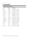
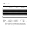
F Interference Gases
The Manning EC-P2 is generally quite specific to the
target gas, but depending on the target gas, other
gases may cause a reading. See Appendix B for a
listing of potential interference gases for the various
SMART-CELLs.
G Alarm Functions
The Manning EC-P2 provides both visible and
audible gas concentration alarms and system
alarms. An alarm condition will be displayed on the
normal operating screen as described on page 8.
In addition to the alarm indication code in the left side
of the screen, an alarm message
will flash inter-
mittently on the screen, the audible beeper
will sound
and the ACK button will appear. Pushing the ACK
button will silence the beeper and stop the display
flashing. The Alarm Indication Code will remain on
the left side of the screen until the alarm condition
clears.
Alarm setpoints are stored on the individual SMART-
CELL and can be changed by the user as described
in Section 4.
NOTE: An audible alarm single beep every
60 seconds indicates that either the Alkaline
C cell battery is low or the internal rechargeable
NiCad battery is low.
H Display Resolution
The Manning EC-P2 displays gas concentration with
a resolution
that depends upon the range of the unit.
Full scale ranges
of 0-4.00 or below will provide
resolution of 0.01. Ranges from 0-5.0 up to 0-49.9 will
provide resolution of 0.1. Full scale ranges above 50
will have a resolution of 1.
Manning EC-P2 Sensor 19546 ECP2 07/09 REVG Copyright © 2009 Honeywell Analytics. All Rights Reserved. 8