3
5. VENTILATION
Any internal combustion engine requires a liberal
supply of cool, clean air for combustion. If the air
entering the engine intake is too warm or too thin,
the engine may not produce its rated power.
Operation of the engine and alternator radiates heat
into the room and raises the temperature of the
room air. Therefore, ventilation of the generator
room is necessary to limit room temperature rise and
to make clean, cool intake air available to the
engine.
When the engine is cooled by a set mounted
radiator, the radiator fan must move large quantities
of air through the radiator core. There must be
enough temperature difference between the air and
the water in the radiator to cool the water
sufficiently before it re-circulates through the
engine. The air temperature at the radiator inlet
depends on the temperature rise of air flowing
through the room from the room inlet ventilator. By
drawing air into the room and expelling it outdoors
through a discharge duct, the radiator fan helps to
maintain room temperature in the desirable range.
In providing ventilation, the objective is to maintain
the room air at a comfortable temperature that is
cool enough for efficient operation and full
available power, but it should not be so cold in
winter that the room is uncomfortable or engine
starting is difficult. Though providing adequate
ventilation seldom poses serious problems, each
installation should be analysed by both the
distributor and the customer to make sure the
ventilation provisions are satisfactory.
5.1 Circulation
Good ventilation requires adequate flow into and
out of the room and free circulation within the room.
Thus, the room should be of sufficient size to allow
free circulation of air, so that temperatures are
equalised and there are no pockets of stagnant air.
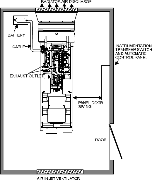
See figure 5.1. The generating set should be
located so that the engine intake draws air from the
cooler part of the room. If there are two or more
generating sets, avoid locating them so that air
heated by the radiator of one set flows toward the
engine intake or radiator fan of an adjacent set. See
figure 5.2.
FIG 5.1 TYPICAL ARRANGEMENT FOR ADEQUATE AIR CIRCULATION AND VENTILATION


