7
6.2 Exhaust Pipe Flexible Section
A flexible connection between the manifold and the
exhaust piping system should be used to prevent
transmitting engine vibration to the piping and the
building, and to isolate the engine and piping from
forces due to thermal expansion, motion or weight
of piping. A well designed flex section will permit
operation with ± 13 mm (0.5 in) permanent
displacement in any direction of either end of the
section without damage. Not only must the section
have the flexibility to compensate for a nominal
amount of permanent mismatch between piping and
manifold, but it must also yield readily to
intermittent motion of the Generating Set on its
vibration isolators in response to load changes.
The flexible connector should be specified with the
Generating Set.
6.3 Exhaust Pipe Insulation
No exposed parts of the exhaust system should be
near wood or other inflammable material. Exhaust
piping inside the building (and the silencer if
mounted inside) should be covered with suitable
insulation materials to protect personnel and to
reduce room temperature. A sufficient layer of
suitable insulating material surrounding the piping
and silencer and retained by a stainless steel or
aluminium sheath may substantially reduce heat
radiation to the room from the exhaust system.
An additional benefit of the insulation is that it
provides sound attenuation to reduce noise in the
room.
6.4 Minimising Exhaust Flow
Restriction
Free flow of exhaust gases through the pipe is
essential to minimise exhaust back pressure.
Excessive exhaust back pressure seriously affects
engine horsepower output, durability and fuel
consumption. Restricting the discharge of gases
from the cylinder causes poor combustion and
higher operating temperatures. The major design
factors that may cause high back pressure are:
• Exhaust pipe diameter too small
• Exhaust pipe too long
• Too many sharp bends in exhaust system
• Exhaust silencer restriction too high
• At certain critical lengths, standing pressure
waves may cause high back pressure
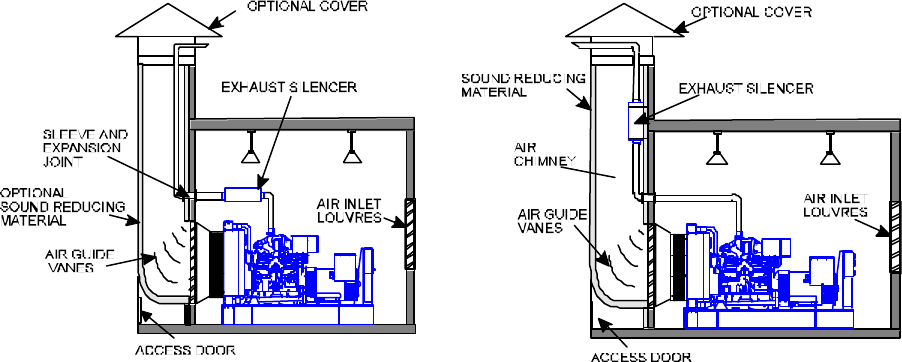
FIG 6.2 HORIZONTALLY MOUNTED EXHAUST SILENCER FIG 6.3 RADIATOR AIR DISCHARGING INTO
WITH EXHAUST PIPE AND RADIATOR AIR SOUND-INSULATED STACK CONTAINING
UTILISING COMMON STACK EXHAUST SILENCER


