8
Excessive restriction in the exhaust system can be
avoided by proper design and construction. To
make sure you will avoid problems related to
excessive restriction, ask The FG Wilson distributor
to review your design.
The effect of pipe diameter, length and the
restriction of any bends in the system can be
calculated to make sure your exhaust system is
adequate without excessive back pressure. The
longer the pipe, and the more bends it contains, the
larger the diameter required to avoid excessive flow
restriction and back pressure. The back pressure
should be calculated during the installation stage to
make certain it will be within the recommended limits
for the engine.
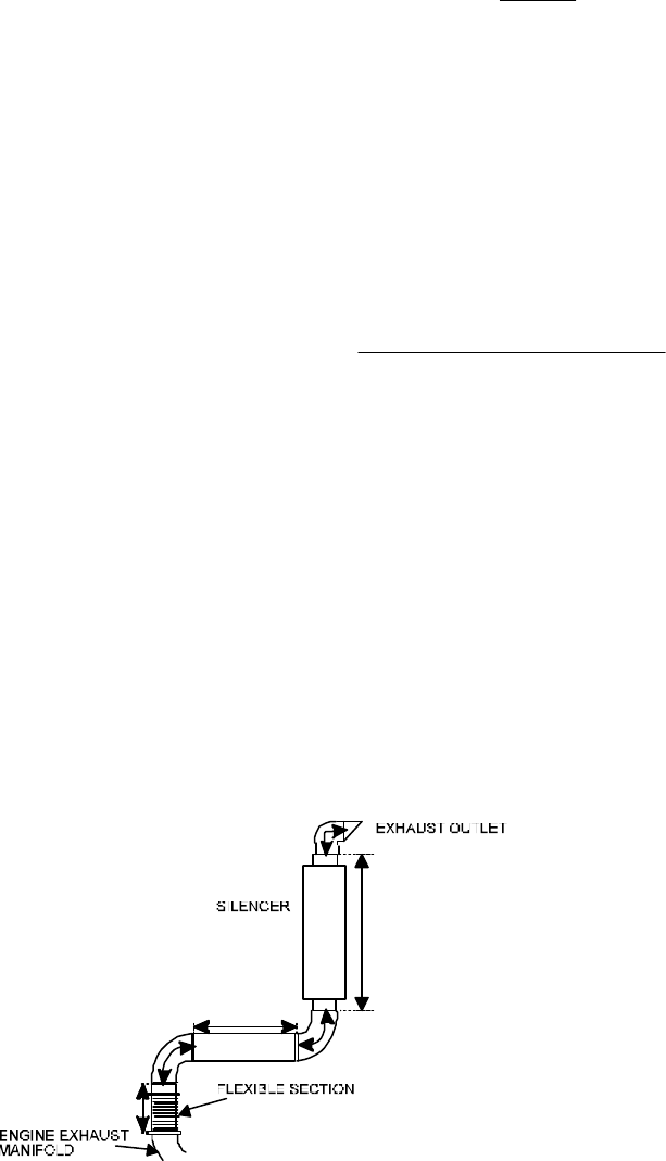
Measure the exhaust pipe length from your
installation layout. See figure 6.4. Take exhaust
flow data and back pressure limits from the
generating set engine specification sheet. Allowing
for restrictions of the exhaust silencer and any
elbows in the pipe, calculate the minimum pipe
diameter so that the total system restriction will not
exceed the recommended exhaust back pressure
limit. Allowance should be made for deterioration
and scale accumulation that may increase restriction
over a period of time.
Elbow restriction is most conveniently handled by
calculating an equivalent length of straight pipe for
each elbow and adding it to the total length of pipe.
For elbows and flexible sections, the equivalent
length of straight pipe is calculated as follows:
45° Elbow:
Length (ft) = 0.75 x Diameter (inches)
90° Elbow:
Length (ft) = 1.33 x Diameter (inches)
Flexible Sections:
Length (ft): 0.167 x Diameter (inches)
The following formula is used to calculate the back
pressure of an exhaust system:
P =
CLRQ
2
D
5
where:
P = back pressure in inches of mercury
C = .00059 for engine combustion airflow of 100 to 400 cfm
= .00056 for engine combustion airflow of 400 to 700 cfm
= .00049 for engine combustion airflow of 700 to 2000 cfm
= .00044 for engine combustion airflow of 2000 to
5400 cfm
L = length of exhaust pipe in feet
R = exhaust density in pounds per cubic foot
R =
41.1
Exhaust temperature
o
F* 460
o
F+
Q = exhaust gas flow in cubic feet per minute*
D = inside diameter of exhaust pipe in inches
* Available from engine specification sheet
These formulae assume that the exhaust pipe is
clean commercial steel or wrought iron. The back
pressure is dependent on the surface finish of the
piping and an increase in the pipe roughness will
increase the back pressure. The constant 41.1 is
based on the weight of combustion air and fuel
burned at rated load and SAE conditions. See
engine specification sheet for exhaust gas
temperature and air flow. Conversion tables to other
units are provided in Section 12.
FIG 6.4 MEASURING EXHAUST PIPE LENGTH TO DETERMINE EXHAUST BACK PRESSURE


