


Remove spark plug wires and position wires away
from plugs.
Remove spark plugs.
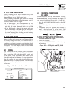
Make sure the piston is at Top Dead Center (TDC)
of its compression stroke (both valves closed). To
get the piston at TDC, remove the intake screen at
the front of the engine to gain access to the flywheel
nut. Use a large socket and socket wrench to rotate
the nut and hence the engine in a clockwise direc-
tion. While watching the piston through the spark
plug hole. The piston should move up and down.
The piston is at TDC when it is at its highest point
of travel.
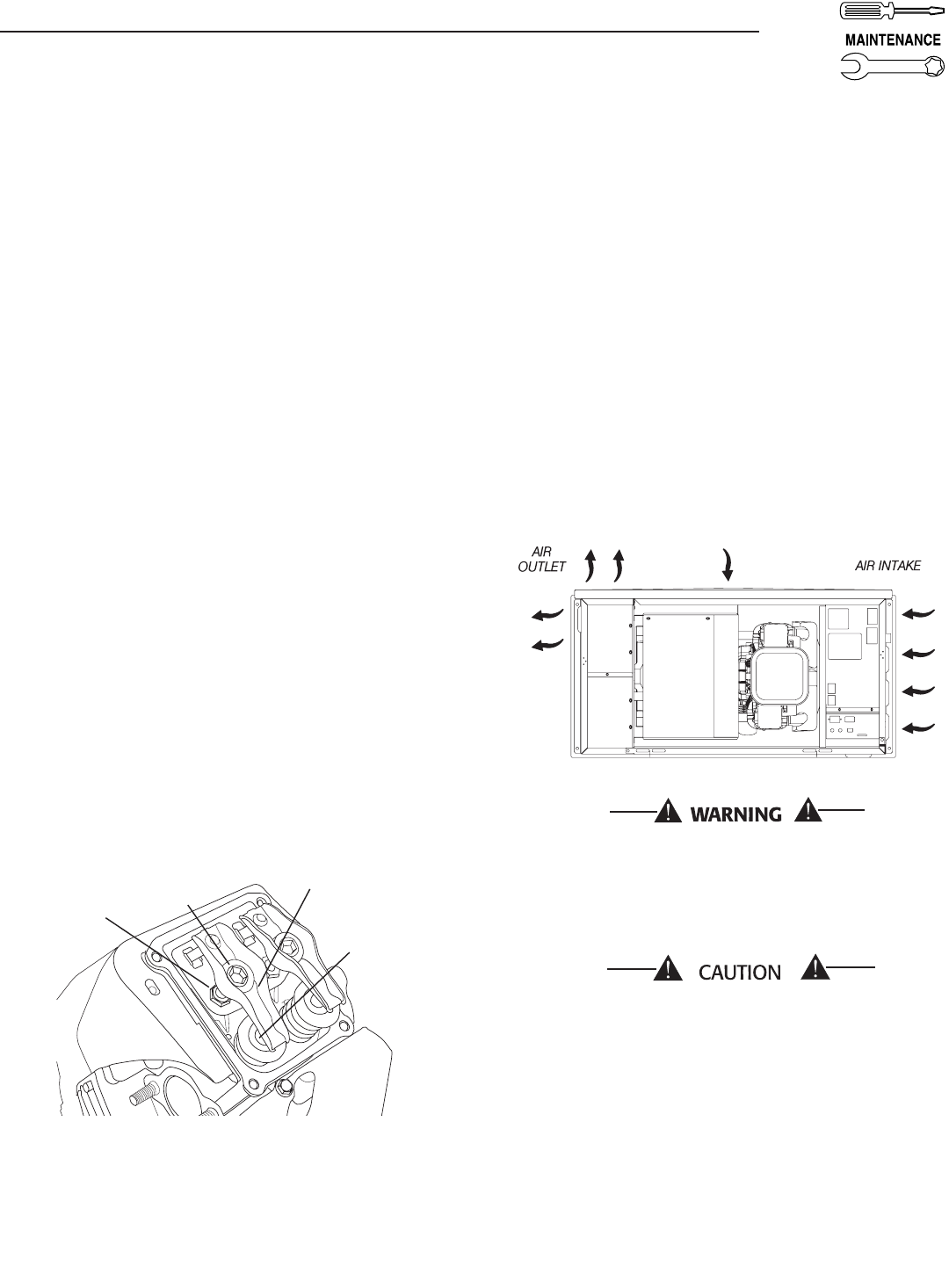
To adjust valve clearance (if necessary):
Make sure the engine is at 60° to 80° F.
Make sure that the spark plug wire is removed
from the spark plug and out of the way.
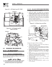
Remove the four screws attaching the valve cover
with a #2 or #3 Phillips screwdriver.
Loosen the rocker jam nut. Use an 10mm allen
wrench to turn the pivot ball stud while checking
clearance between the rocker arm and the valve
stem with a feeler gauge. Correct clearance is
0.002-0.004 inch (0.05-0.1 mm).
NOTE:
Hold the rocker arm jam nut in place as the pivot
ball stud is turned.
When valve clearance is correct, hold the pivot ball
stud in place with the allen wrench and tighten the
rocker arm jam nut. Tighten the jam nut to 174
in/lbs. torque. After tightening the jam nut, recheck
valve clearance to make sure it did not change.
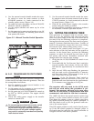
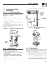
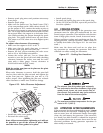
Figure 4.10 - Valve Clearance Adjustment
Jam Nut
Pivot Ball
Stud
Rocker
Arm
Valve
Stem
Install new valve cover gasket.
Re-attach the valve cover.
NOTE:
Start all four screws before tightening or it will not
be possible to get all the screws in place. Make
sure the valve cover gasket is in place.
•
•
•
•
•
•
•
•
•
Install spark plugs.
Re-attach the spark plug wire to the spark plug.
On the GT-530 and GT-990, repeat the process for
the other cylinder.
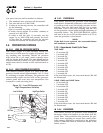
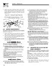
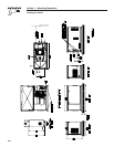
4.8 COOLING SYSTEM
Air inlet and outlet openings in the generator com-
partment must be open and unobstructed for con-
tinued proper operation. This includes such obstruc-
tions as high grass, weeds, brush, leaves and snow.
Without sufficient cooling and ventilating air flow, the
engine/generator quickly overheats, which causes it
to quickly shut down. (See Figure 4.11 for vent loca-
tions.)
Make sure the doors and roof are in place dur-
ing operation as running the generator with them
removed can effect cooling air movement.
Figure 4.11 – Cooling Vent Locations
The exhaust from this product gets extremely
hot and remains hot after shutdown. High grass,
weeds, brush, leaves, etc. must remain clear of
the exhaust. Such materials may ignite and burn
from the heat of the exhaust system.
The maximum ambient temperature for the gen-
erator is 40° C (104° F).
4.9 ATTENTION AFTER SUBMERSION
If the generator has been submerged in water, it must
not be started and operated. Following any submer-
sion in water, have an Authorized Dealer thoroughly
clean, dry and inspect the generator. If the structure
(ex. home) has been flooded, it should be inspected
by a certified electrician to ensure there won't be any
electrical problems during generator operation or
when utility is returned.
•
•
•
23
Section 4 — Maintenance
Air-cooled Generators