


16
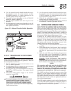
3.1.4 CHOKE OPERATION
1. 990 engines have an electric choke in the air box
that is automatically controlled by the electronic
control board.
2. 530 engines have an electric choke on the divider
panel air inlet hose that is automatically con-
trolled by the electronic control board.
3. 410 engines do not have a choke.
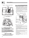
3.2 AUTOMATIC TRANSFER
OPERATION
To select automatic operation, do the following:
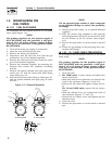
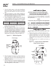
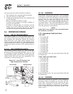
1. Make sure the transfer switch main contacts are
set to their UTILITY position, i.e., loads con-
nected to the utility power source (Figure 3.2).
2. Be sure that normal UTILITY power source volt-
age is available to transfer switch terminal lugs
N1 and N2 (Refer to the Electrical Data section).
3. Set the generator’s AUTO/OFF/MANUAL switch to
AUTO.
4. Set the generator’s main circuit breaker to its ON
(or CLOSED) position.
With the preceding steps complete, the generator will
start automatically when utility source voltage drops
below a preset level. After the unit starts, loads are
transferred to the standby power source. Refer to the
Sequence of Automatic Operation section.
3.3 SEQUENCE OF AUTOMATIC
OPERATION
The generator’s control panel houses a control logic
circuit board. This board constantly monitors util-
ity power source voltage. Should that voltage drop
below a preset level, circuit board action will signal
the engine to crank and start. After the engine starts,
the circuit board signals the transfer switch to acti-
vate and connect load circuits to the standby power
supply (load terminal lugs T1/T2 connect to terminal
lugs E1/E2). Refer to the Electrical Data section.
The generator must run at 50 Hz or greater for the
transfer output to be activated. Once activated, it will
remain active even if the frequency dips below 50
Hz.
Upon restoration of utility source voltage above a
preset level, generator circuit board action signals the
transfer switch to transfer loads back to that power
supply. After retransfer, the engine is signalled to shut
down.
The actual sequence of operation is controlled by
sensors and timers on a control logic circuit board,
as follows:
A. Utility Voltage Dropout Sensor
• This sensor monitors utility source voltage.
• If utility source voltage drops below about 65
percent of the nominal supply voltage, the sensor
energizes a 10 second timer.
• Once the timer has expired, the engine will crank
and start if utility is still low.
B. Engine Warm-up Time Delay
• This mechanism lets the engine warm up for
about five (5) seconds before the load is trans-
ferred to the standby source.
C. Standby Voltage Sensor
• This sensor monitors generator AC output volt-
age. When the voltage has reached 50 percent of
the nominal rated voltage, transfer to standby
can occur.
D. Utility Voltage Pickup Sensor
• This sensor monitors utility power supply volt-
age. When that voltage is restored above 75 per-
cent of the nominal source voltage, a retransfer
time delay starts timing.
E. Retransfer Time Delay
• This timer runs for about 15 seconds.
• At end of a 15-second delay, circuit board action
de-energizes transfer relay in the transfer switch
if utility is still present.
• Retransfer to utility power source then occurs.
F. Engine Cool-down Timer
• When the load is transferred back to utility power
source, the engine cool-down timer starts tim-
ing.
• The timer will run for about one minute, and the
generator will then shut down.
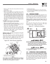
3.4 MANUAL TRANSFER OPERATION
3.4.1 TRANSFER TO GENERATOR
POWER SOURCE
To start the generator and activate the transfer switch
manually, proceed as follows:
1. Set the generator’s AUTO/OFF/MANUAL switch to
OFF.
2. Set the generator’s main circuit breaker to its
OFF (or OPEN) position.
3. Turn OFF the utility power supply to the transfer
switch using the means provided (such as a utility
main line circuit breaker).
DANGER
Do not attempt to activate the transfer switch
manually until all power voltage supplies to the
switch have been positively turned off. Failure
to turn off all power voltage supplies may result
in extremely hazardous and possibly fatal elec-
trical shock.
Section 3 — Operation
Air-cooled Generators