


12
2.1 BEFORE INITIAL START-UP
NOTE:
These units have been run and tested at the fac-
tory prior to being shipped and do not require any
type of break-in.
Before starting, complete the following:
1. Set the generator’s main circuit breaker to its
OFF (or OPEN) position.
2. Set the generator's AUTO/OFF/MANUAL switch to
the OFF position.
3. Turn OFF all breakers on the load center of the
transfer box (T1 and T2).
4. Turn OFF all loads connected to the transfer
switch terminals T1 and T2.
5. Check the engine crankcase oil level and, if neces-
sary, fill to the dipstick FULL mark with the rec-
ommended oil. Do not fill above the FULL mark.
6. Check the fuel supply. Gaseous fuel lines must
have been properly purged and leak tested in
accordance with applicable fuel-gas codes. All
fuel shutoff valves in the fuel supply lines must
be open.
Never operate the engine with the oil level
below the “Add” mark on the dipstick. Doing
this could damage the engine.
2.2 CHECK TRANSFER SWITCH
OPERATION
Refer to the "Manual Transfer Operation" section, of
the owner’s manual for procedures.
DANGER
Do not attempt manual transfer switch opera-
tion until all power voltage supplies to the
transfer switch have been positively turned off.
Failure to turn off all power voltage supplies
will result in extremely hazardous and possibly
fatal electrical shock.
2.3 ELECTRICAL CHECKS
Complete electrical checks as follows:
1. Set the generator's main circuit breaker to its
OFF (or OPEN) position.
2. Set the generator's AUTO/OFF/MANUAL switch to
the OFF position.
3. Turn OFF all breakers on the load center of the
transfer box (T1 and T2).
4. Turn on the utility power supply to the transfer
switch using the means provided (such as a utility
main line circuit breaker).
DANGER
The transfer switch is now electrically “hot.”
Contact with “hot” parts will result in extremely
hazardous and possibly fatal electrical shock.
Proceed with caution.
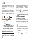
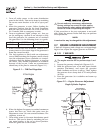
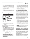
5. Use an accurate AC voltmeter to check utility
power source voltage across transfer switch ter-
minals N1 and N2. Nominal line-to-line voltage
should be 240 volts AC.
6. Check utility power source voltage across termi-
nals N1 and the transfer switch neutral lug; then
across terminal N2 and neutral. Nominal line-to-
neutral voltage should be 120 volts AC.
7. When certain that utility supply voltage is compat-
ible with transfer switch and load circuit ratings,
turn OFF the utility power supply to the transfer
switch.
8. On the generator panel, set the AUTO/OFF/
MANUAL switch to MANUAL. The engine should
crank and start.
9. Let the engine warm up for about five minutes to
allow internal temperatures to stabilize. Then, set
the generator’s main circuit breaker to its ON (or
CLOSED) position.
DANGER
Proceed with caution! Generator power voltage
is now supplied to the transfer switch. Contact
with live transfer switch parts will result in dan-
gerous and possibly fatal electrical shock.
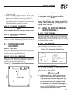
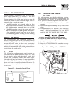
10. Connect an accurate AC voltmeter and a frequen-
cy meter across transfer switch terminal lugs E1
and E2. 7kW voltage should be 242-252 volts at
a frequency of 61-63 Hertz. 10, 13, and 16kW
voltage should be 250-252 volts at a frequency of
57.5-59.5 Hertz.
11. Connect the AC voltmeter test leads across ter-
minal lugs E1 and neutral; then across E2 and
neutral. In both cases, voltage reading should be
121-126 volts AC (7kW), and 125-126 volts AC
(10, 13 and 16kW).
12. Set the generator’s main circuit breaker to its
OFF (or OPEN) position. Let the engine run at no-
load for a few minutes to stabilize internal engine
generator temperatures.
13. Set the generator's AUTO/OFF/MANUAL switch to
OFF. The engine should shut down.
NOTE:
It is important not to proceed until certain that
generator AC voltage and frequency are correct
and within the stated limits. Generally, if both AC
frequency and voltage are high or low, the engine
governor requires adjustment* (*GH410 only). If
frequency is correct, but voltage is high or low, the
generator’s voltage regulator requires adjustment.
Section 2 — Post Installation Start-up and Adjustments
Air-cooled Generators