


19
3.6.5 RPM SENSOR FAILURE
During cranking, if the board does not see a valid
RPM signal within three (3) seconds, it will shut
down and latch out on RPM sensor loss.
During running, if the RPM signal is lost for one full
second the board will shut down the engine, wait 15
seconds, then re-crank the engine.
If an RPM signal is not detected within the first
three (3) seconds of cranking, the control board
will shut the engine down and latch out on RPM
sensor loss.
If the RPM signal is detected the engine will start
and run normally. If the RPM signal is subsequent-
ly lost again, the control board will try one more
re-crank attempt before latching out and flashing
the overspeed LED.
3.6.6 LOW BATTERY
The microprocessor will continually monitor the
battery voltage and turn on the Low Battery LED if
the battery voltage falls below 11.0 volts for one (1)
minute. No other action is taken on a low battery
condition. Low battery voltage is a non-latching alarm
which will automatically clear if the battery voltage
rises above 11.0 volts. Battery voltage is NOT moni-
tored during the crank cycle.
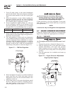
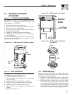
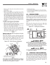
4.1 FUSES
The 15-amp fuse on the generator panel protects the
DC control circuit against overload (Figure 4.1). This
fuse is wired in series with the battery output lead
to the panel. If this fuse element has melted open,
the engine will not be able to crank or start. Replace
this fuse using only an identical 15-amp replacement
fuse. To replace the fuse, push the fuse holder cap
down and rotate it counterclockwise. Whenever the
fuse is removed or replaced, the exercise timer needs
to be reset.
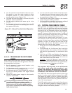
Figure 4.1 – Generator Control Panel
OFF
EXERCISE
SYSTEM FUSE
15A
ASSY: 0F8418/0F8419
SET
TIME
AUTO. MAN.
NO UTILITY SENSE
5 FLASHING RED LEDS=
EXERCISER NOT SET
FLASHING GREEN LED=
SYSTEM SET
NO RPM SENSE IF FLASHING
OVER SPEED
CONTROL AND INFORMATION CENTER
LOW BATTERY
LOW OIL
HIGH TEMP
OVER CRANK
•
•
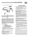
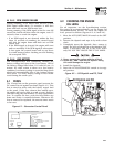
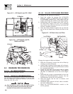
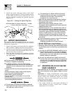
4.2 CHECKING THE ENGINE
OIL LEVEL
For oil capacities, see the Specifications section.
For engine oil recommendations, see the Engine Oil
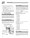
Recommendations section. To check the engine oil
level, proceed as follows (Figures 4.2, 4.3 and 4.4):
1. Move the AUTO/OFF/ MANUAL switch to the OFF
position.
2. Remove the dipstick and wipe it dry with a clean
cloth.
3. Completely insert the dipstick; then, remove it
again. The oil level should be at the dipstick “Full”
mark. If necessary, add oil to the “Full” mark
only. DO NOT FILL ABOVE THE “FULL” MARK.
Never operate the engine with the oil level
below the “Add” mark on the dipstick. Doing
this could damage the engine.
4. Install the dipstick.
5. Reset the AUTO/OFF/MANUAL switch to its origi-
nal position.
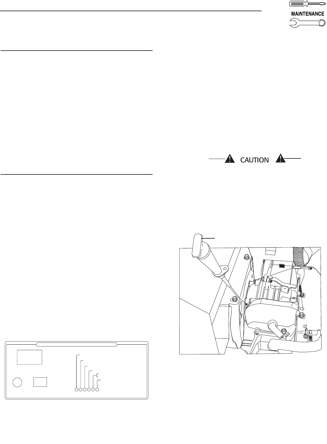
Figure 4.2 — Oil Dipstick and Fill, 7kW
Oil Dipstick and Fill
Section 4 — Maintenance
Air-cooled Generators