


15
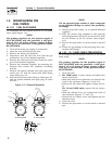
4. Connect a frequency meter across the generators
AC output leads.
5. Turn the primary adjust screw to obtain a fre-
quency reading of 61.5 Hertz. Turn the secondary
adjust screw to obtain a frequency of 62.5 Hz.
6. When frequency is correct at no load, check the
AC voltage reading. If voltage is incorrect, the volt-
age regulator may require adjustment (See the
Voltage Regulator Adjustment section).
2.7.2 13 KW AND 16 KW UNITS
NOTE:
All V-twin units DO NOT require an engine gover-
nor adjustment due to their design.
2.7.3 ADDITIONAL CORROSION
PROTECTION
Periodically spray all engine linkage parts and brack-
ets with corrosion inhibiting spray such as WD-40 or
a comparable product.
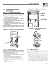
2.8 VOLTAGE REGULATOR
ADJUSTMENT
2.8.1 7KW UNITS
With the frequency between 62-63 Hertz at no-load,
slowly turn the slotted potentiometer (Figure 2.3)
until line voltage reads 248-252 volts.
2.8.2 10, 13, AND 16KW UNITS
With the frequency between 58-59 Hertz at no-load,
slowly turn the slotted potentiometer (Figure 2.3)
until line voltage reads 232-236 volts.
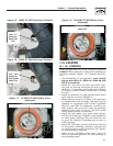
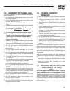
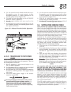
Figure 2.3 – Voltage Adjustment Potentiometer
Turn to
adjust voltage.
NOTE:
The access panel on top of the control panel must
be removed to adjust the voltage regulator.
NOTE:
The voltage regulator is housed above the gen-
erator's control panel. The regulator maintains a
voltage in direct proportion to frequency at a 2-to-
1 ratio. For example, at 62 Hertz, line-to-neutral
voltage will be 124 volts.
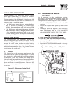
3.1 USING THE AUTO/OFF/MANUAL
SWITCH (FIGURE 3.1)
3.1.1 “AUTO” POSITION
Selecting this switch position activates fully automatic
system operation. It also allows the unit to automati-
cally start and exercise the engine every seven days
with the setting of the exercise timer (see the Setting
the Exercise Timer section).
3.1.2 “OFF” POSITION
This switch position shuts down the engine. This
position also prevents automatic operation.
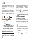
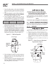
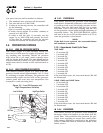
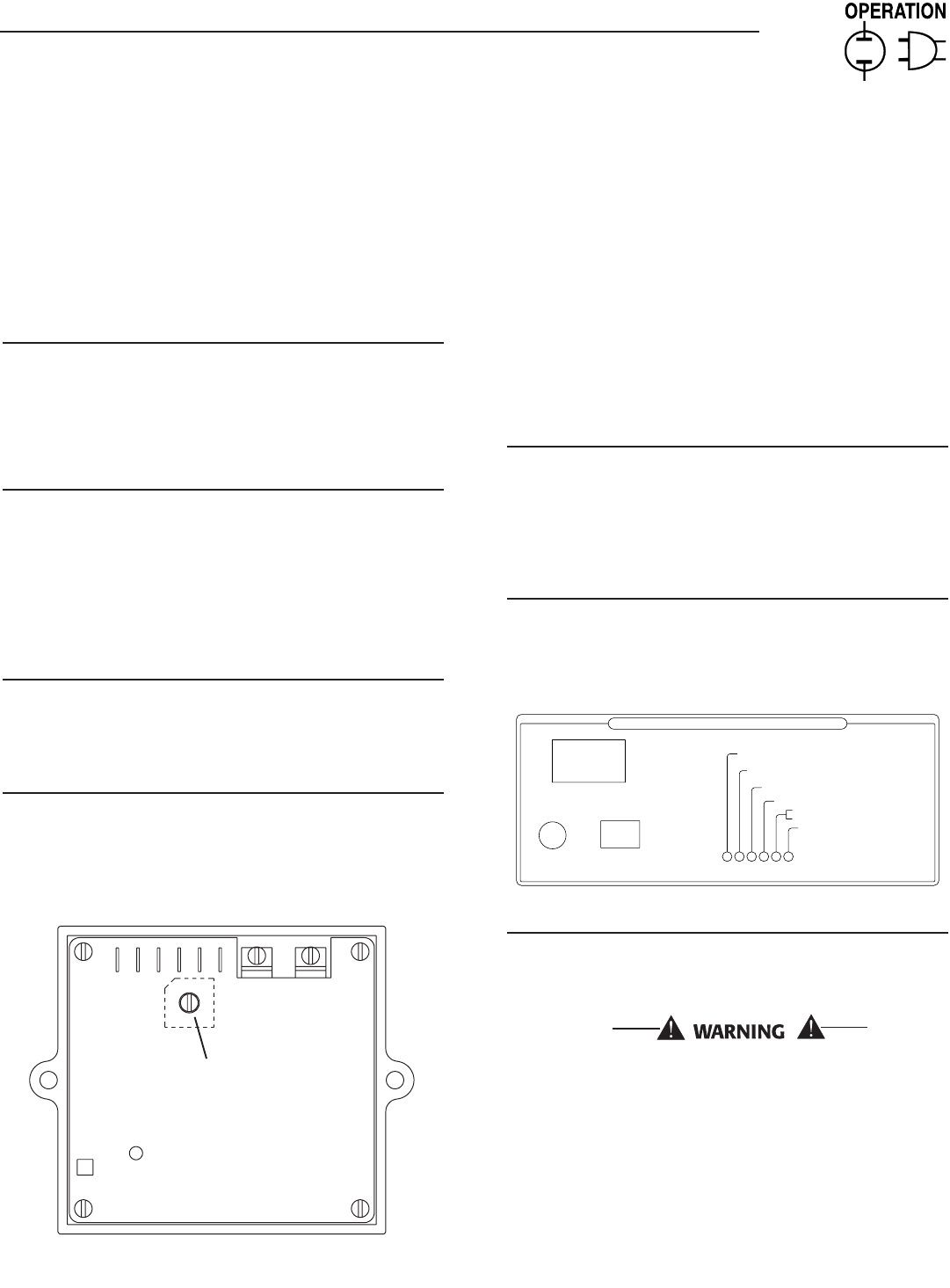
Figure 3.1 – Generator Control Panel
OFF
EXERCISE
SYSTEM FUSE
15A
ASSY: 0F8418/0F8419
SET
TIME
AUTO. MAN.
NO UTILITY SENSE
5 FLASHING RED LEDS=
EXERCISER NOT SET
FLASHING GREEN LED=
SYSTEM SET
NO RPM SENSE IF FLASHING
OVER SPEED
CONTROL AND INFORMATION CENTER
LOW BATTERY
LOW OIL
HIGH TEMP
OVER CRANK
3.1.3 “MANUAL” POSITION
Set the switch to MANUAL to crank and start the
engine. Transfer to standby power will not occur
unless there is a utility failure.
With the switch set to AUTO, the engine may
crank and start at any time without warning.
Such automatic starting normally occurs when
utility power source voltage drops below a pre-
set level or during the normal exercise cycle. To
prevent possible injury that might be caused
by such sudden starts, always set the switch to
OFF and remove the fuses before working on or
around the generator or transfer switch. Then,
place a “DO NOT OPERATE” tag on the genera-
tor panel and on the transfer switch.
Section 3 — Operation
Air-cooled Generators