


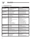

NOTE:
Balance must be maintained when moving circuit locations
from main electrical distribution panel to emergency load
center. Circuit breaker positions alternate buss bars vertically.
Circuits sharing a neutral wire should either be moved together
to adjacent positions in emergency load center or not moved. If
you are unsure of proper procedure or if your installation differs
from that described in this guide, consult a licensed professional
at this time.
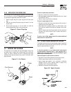
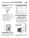
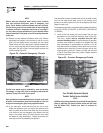
10a. Remove the main electrical distribution panel cover. Remove
appropriate size knockout from the bottom or side of the main
panel. (A 2-foot flexible conduit is pre-wired from the manual
transfer switch with built-in load center). Remove threaded lock
nut from conduit coupling. Feed all wires through knockout into
main panel. Slip lock nut over wires and tighten securely onto
conduit coupling (Figure 33).
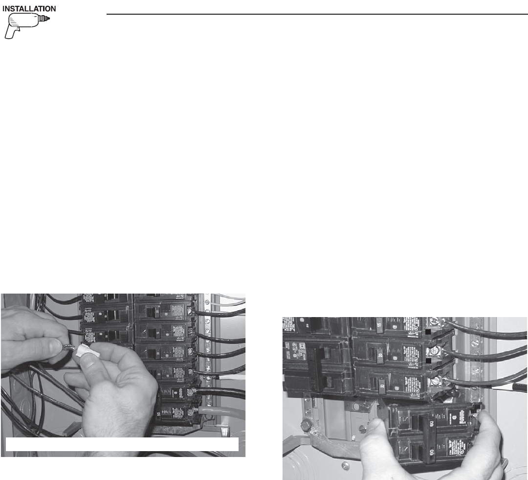
Figure 33 - Connect Emergency Circuits
NOTE:
Circuits to be moved must be protected by same size breaker.
For example, a 15 amp 120V circuit in emergency load center will
replace a 15 amp 120V circuit in main panel.
NOTE:
Both grounded and ungrounded conductors for each circuit must
be moved to the emergency panel and connected to to the new
wiring from the emergency panel using supplied locknuts.
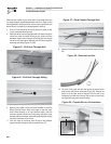
10b. In your main panel, remove the black (hot) wire from a circuit
breaker that protects a circuit you want to have powered in the
event of a power failure. Wire nut the black wire to the matching
circuit lead wire from the emergency circuit breaker from load
center in the transfer switch. (All circuit wires are color coded
and labeled for easy identification). Repeat this process with
remaining circuits to be powered by the generator.
Trace each black (hot) wire connected and wire nut the white (neutral)
wire from the same Romex cable (circuit) to the matching circuit
number on the white (neutral) wire from the emergency load center.
Repeat for each circuit.
The emergency load center in the transfer switch supplies the following
circuits: (5) 15A/120V, (5) 20A/120V, (1) 20A/240V, (1) 40A/240V and
(1) 50A/240V.
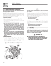
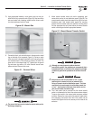
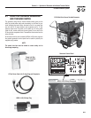
11. Install the 60 Amp double pole circuit breaker that you have
purchased into main electrical distribution panel (Figure 34).
This circuit breaker must be compatible with your main
electrical distribution panel. It may be necessary to reposition
remaining circuit breakers or remove circuit breakers that have
been disconnected to accommodate the insertion of the 60
Amp double pole circuit breaker. Connect white wire to the main
distribution panel neutral bar. Connect solid green wire to main
electrical panel ground bar. Connect the black and red wires
to the 60 Amp double pole circuit breaker. Replace electrical
distribution panel cover.
Figure 34 - Connect Emergency Circuits
Your Portable Generator Manual
Transfer Switch is now installed.
NOTE:
If additional circuits are required to be protected. The manufacturer
offers an additional 30A manual transfer switch and 30A Power
Inlet Kit (Model 5341). Contact your place of purchase for
availability.
UL approved wire nuts are included with installation kit.
60
60
Section 5 — Installation for Manual Transfer Switch
Portable Generator System
22