


7
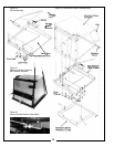
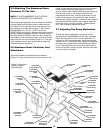
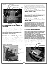
2-3 Attaching The Top Main Frame
Assembly
Place the top main frame assembly P#(00197800)
(Figure 9) onto the main frame legs and fasten each side
by using (1) 3/4”-10 x 1-1/2” HHCS P#(05959600), (1)
3/4”-10 nyloc nut P#(06540800), (1) ½”-13 x 1” HHCS
P#(05947100), and (1) pivot frame handle
P#(00194900). The handles are used to pivot the frame
to the rear for mower engine access. Be sure that the
handles are tight and the frame is in the upright position
before each use!
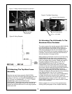
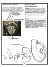
2-4 Attaching The Lift Handle To The
Aluminum Grass Container
The various parts of the handle assembly P#(00192100)
must be attached to the container frame. Figure 10
shows the orientation and location of the components.
Slide the lift handle into the slot in the handle mount
bracket P#(00193500) on the grass container. It may be
necessary to remove the handle grip P#(07538700) to
allow the handle to fit through the slot.
Before attaching the handle, hook one end of the spring
P#(08354400) into the hole on the underside of the
handle. Hook the other end of the spring into the open
hole in the handle mount bracket. Fasten the handle to
the grass container frame by using (1) 3/8”-16 x 2”
HHCS P#(05963300) and (2) 3/8”-16 flange nuts
P#(06542000). At this point the handle can pivot back
and forth in the slot of the handle mount bracket. With
the handle in place, fasten the ball joint P#(00192400) to
the end of the latch rod P#(00192300) (Figure 12).
Tighten to approximately half way down the threads of
the latch rod. Slide the ball joint into the hole on the latch
hook P#(00192500). Use (1) 5/16”-24 hex nut
P#(06529500) and (1) 5/16” lock washer P#(06308600)
to fasten the ball joint to the latch hook. Attach the
opposite end of the latch rod into the handle. Fasten the
rod to the handle by using (1) 3/32” x 3/4” cotter pin
P#(06706900). Adjust the rod to allow the hook to close
the box door completely.
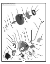
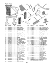
Refer to pages 9,10,11,12 and 13 for exploded parts
drawings and photographs of the complete assembly.
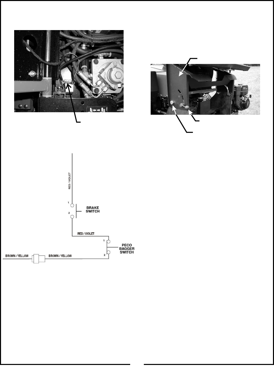
Figure 9 Top Main Frame Assy.
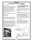
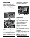
Figure 7 Safety Interlock Harness Connections
Figure 8 Wiring Diagram
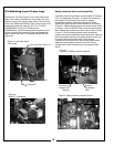
Parking Brake
Switch Bolts
Top Main Frame Assembly
Pivot Frame Handle
3/4” x 1-1/2” HHCS