


13
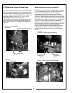
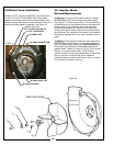
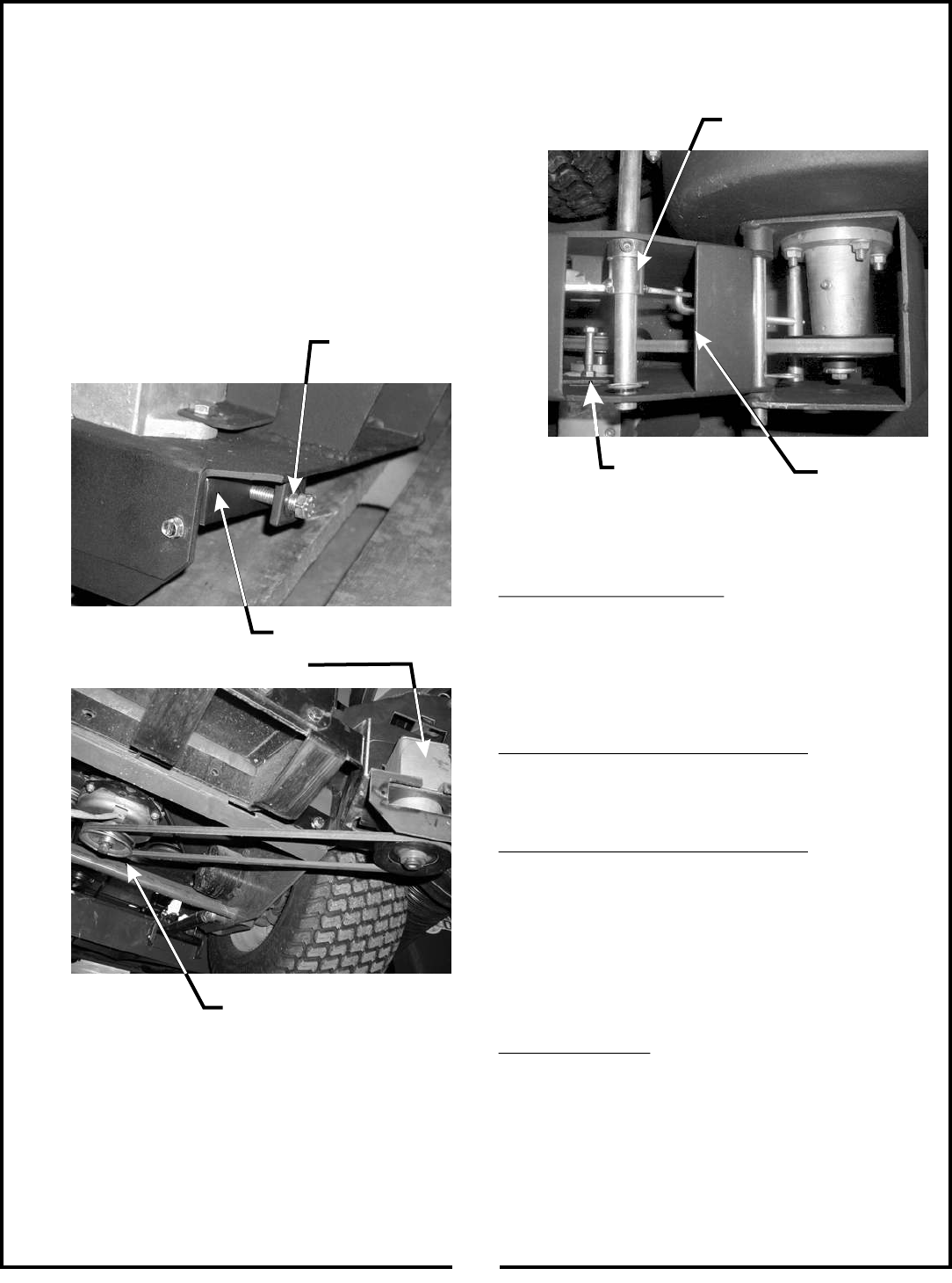
2-11 Cam Assembly Adjustment
The cam assembly P#(00196900), which controls the
blower belt tension, comes from the factory pre-adjusted.
If the belt is too tight or becomes too loose, remove the
hair pin clip P#(06713500) from the belt tension rod
P#(00196800) and pull the “L” end of the rod out of its
hole in the cam assembly. The tension rod may then be
screwed out to tighten the belt or screwed in to loosen
the belt. Replace the “L” end into the top hole in the cam
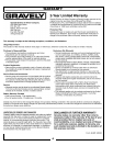
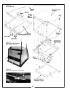
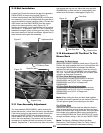
2-10 Belt Installation
Loosen the (2) bolts that secure the gear box assembly
P#(00197300) to the pto mount plate (Figure 17).
Loosen the adjustment bolt P#(05942200) until the gear
box assembly is at its far left adjustment (the gear box is
moved towards the mower’s engine pulley). Connect the
A56K kevlar cord belt P#(07243400) from the engine
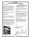
pulley to the lower gear box pulley (Figure 18). To
tension the drive belt, turn the adjustment bolt clockwise
until there is 1” of deflection, with 10-11 lbs. of pressure
between the engine pulley and the gear box pulley. Once
the correct tension of the belt is achieved, tighten the (2)
bolts that secure the gear box assembly.
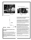
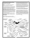
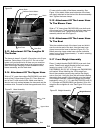
2-12 Attachment Of The Boot To The
Mower Deck
Mounting The Boot Hanger
Remove the mower’s deflector shield mount (Figure 20).
Position the notch towards the front of unit and place the
boot hanger P#(00194400) in-between the deflector
shield mount and the mower deck. Fasten by using (3)
3/8”-16 x 1-1/4” HHCS P#(05958000) and the existing
3/8” nuts. The boot hanger will allow you to switch from
collection to discharge in seconds.
60” Boot Plate Mounting Instructions
To mount the boot plate P#(00194300) to the boot
P#(00194200) use (3) 3/8”-16 x 1” carriage bolts
P#(06223600) and (3) 3/8”-16 flange nuts
P#(06542000).
52” Boot Plate Mounting Instructions
To mount the boot plate P#(00194600) to the boot
P#(00194500) use (2) 3/8”-16 x 3/4” carriage bolts
P#(06223900) and (2) 3/8”-16 flange nuts
P#(06542000).
Note: When bolting the boot and boot plate together,
the head of the bolt is placed from the inside of the boot.
This will prevent grass from collecting on the bolts.
For All Deck Sizes
Remove the bolts from that hold the deflector shield in
place so that the boot rod can fasten the boot and boot
plate to the mower deck. Align the holes in the boot plate
to the holes in the deflector shield mount and slide the
boot rod P#(00254500 (60” Deck) 00254700 (52” deck))
through and fasten using (1) hair pin clip P#(06713500).
Note: The Mower’s Deflector Shield Has Been
Removed In The Following Photo For Clarity. Always
have the deflector shield mounted when mowing.
and replace the hair pin clip. Adjust the cam stop bolt
P#(05980900) to allow the cam to rotate slightly over
center when the blower is disengaged (Figure 19).
Gear Box Assy.
Adjustment Bolt
PTO Mount Plate
Engine Pulley
Figure 17
Figure 18
Cam Assy.
Tension Rod
Figure 19
Cam Stop Bolt