


6
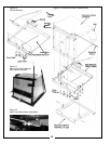
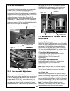
2-2 Attaching Lower Frame Legs
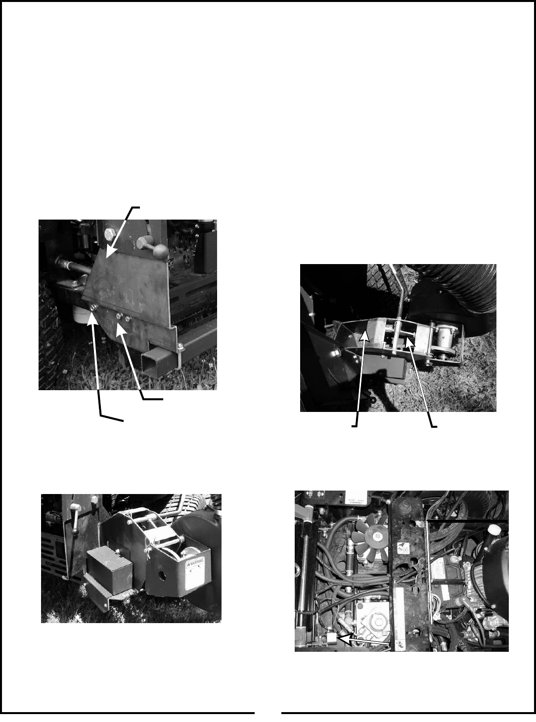
Remove the (3) bolts (Figure 3) from each side of the
rear of the mower. Keep the bolt, from each side, that
threads through the mower’s rear frame. Place the left
lower main frame leg P#(00197700) onto the rear of the
mower and fasten by using (2) 3/8”-16 x 3” HHCS
P#(05957800) and (2) 3/8”-16 flange nuts
P#(06542000). Use the existing bolt removed from the
mower to fasten the front side of the leg. Repeat this
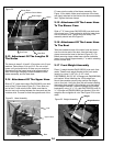
step to fasten the right PTO assembly P#(00195500)
(Figure 4).
Figure 3 Left Lower Main
Frame Leg.
3/8” x 3” HHCS
Figure 4
Right PTO Assembly
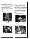
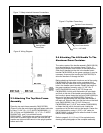
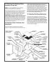
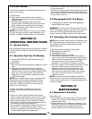
Safety Interlock Harness Connection
The safety interlock harness is located inside of the right
PTO arm assembly (Figure 5). To install the harness to
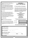
the mower, lift the hood of the mower for engine
compartment access. Route the harness as shown
towards the parking brake switch bracket on the mower
(Figure 6). Fasten the harness to the mower’s rear frame
by using (1) zip tie P#(07517300) to prevent the harness
from rubbing the mower’s tire. Next, remove the (2) bolts
(Figure 7) from the parking brake switch bracket for
access to the brown/yellow and red/violet wires. Remove
the brown/yellow wire from the parking brake switch and
connect to the brown/yellow wire of the harness.
Connect the red/violet wire to the parking brake switch,
where the brown/yellow wire was removed (Figure
8).Replace the bolts removed from the parking brake
switch.
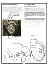
Figure 5
Location Of Safety Interlock Harness
Harness
Connected
Here
Free End Of
Harness For
Routing
Figure 6 Safety Interlock Harness Route
Left Lower Main Frame Leg
Existing Bolt