


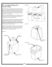
2-3 Attaching The Top Main Frame
Assembly
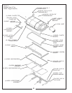
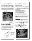
Place the top main frame assembly P#(00197800)
(Figure 9) onto the main frame legs and fasten each side
by using (1) 3/4”-10 x 1-1/2” HHCS P#(05959600), (1)
3/4”-10 nyloc nut P#(06540800), (1) ½”-13 x 1” HHCS
P#(05947100), and (1) pivot frame handle
P#(00194900). The handles are used to pivot the frame
to the rear for mower engine access. Be sure that the
handles are tight and the frame is in the upright position
before each use!
2-3 Attaching The Top Main Frame
Assembly
Place the top main frame assembly P#(00197800)
(Figure
9) onto the main frame legs and fasten each side
by
using (1) 3/4”-10 x 1-1/2” HHCS P#(05959600), (1)
3/4”-10
nyloc nut P#(06540800), (1) ½”-13 x 1” HHCS
P#(05947100),
and (1) pivot frame handle
P#(00194900). The
handles are used to pivot the frame
to
the rear for mower engine access. Be sure that the
handles
are tight and the frame is in the upright position
before
each use!
7
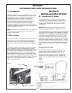
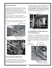
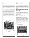
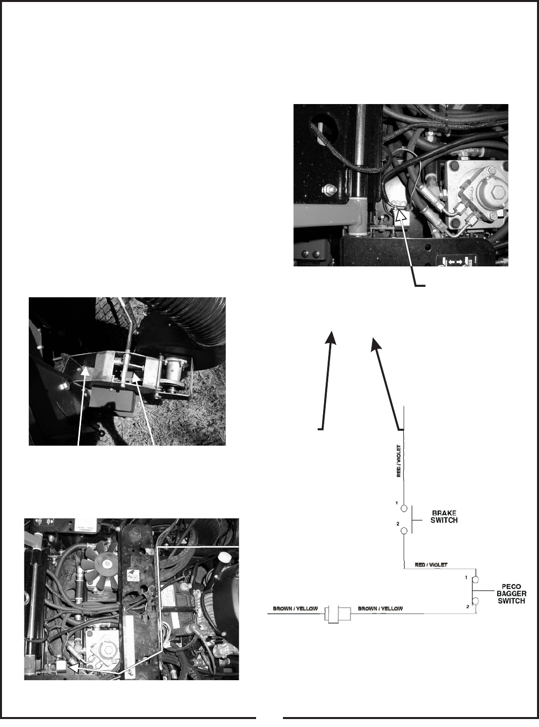
2-4 Safety Interlock Harness
Connection
The safety interlock harness is located inside of the right
PTO arm assembly (Figure 7). To install the harness to
the mower, lift the hood of the mower for engine
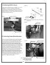
compartment access. Route the harness as shown
towards the parking brake switch bracket on the mower
(Figure 8). Fasten the harness to the mower’s rear frame
by using (1) zip tie P#(J0245) to prevent the harness
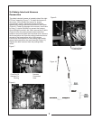
from rubbing the mower’s tire. Next, remove the (2) bolts
(Figure 9) from the parking brake switch bracket for
access to the brown/yellow and red/violet wires. Remove
the brown/yellow wire from the parking brake switch and
connect to the brown/yellow wire of the harness.
Connect the red/violet wire to the parking brake switch,
where the brown/yellow wire was removed (Figure 10).
Replace the bolts removed from the parking brake
switch.
Figure 9.
Figure 10.
Figure 7.
Figure 8.
Free End Of
Harness For
Routing
Harness
Connected
Here
Parking Brake
Switch Bolts