


13
2-11 Adjustment Of The Lengths Of
Hoses
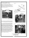
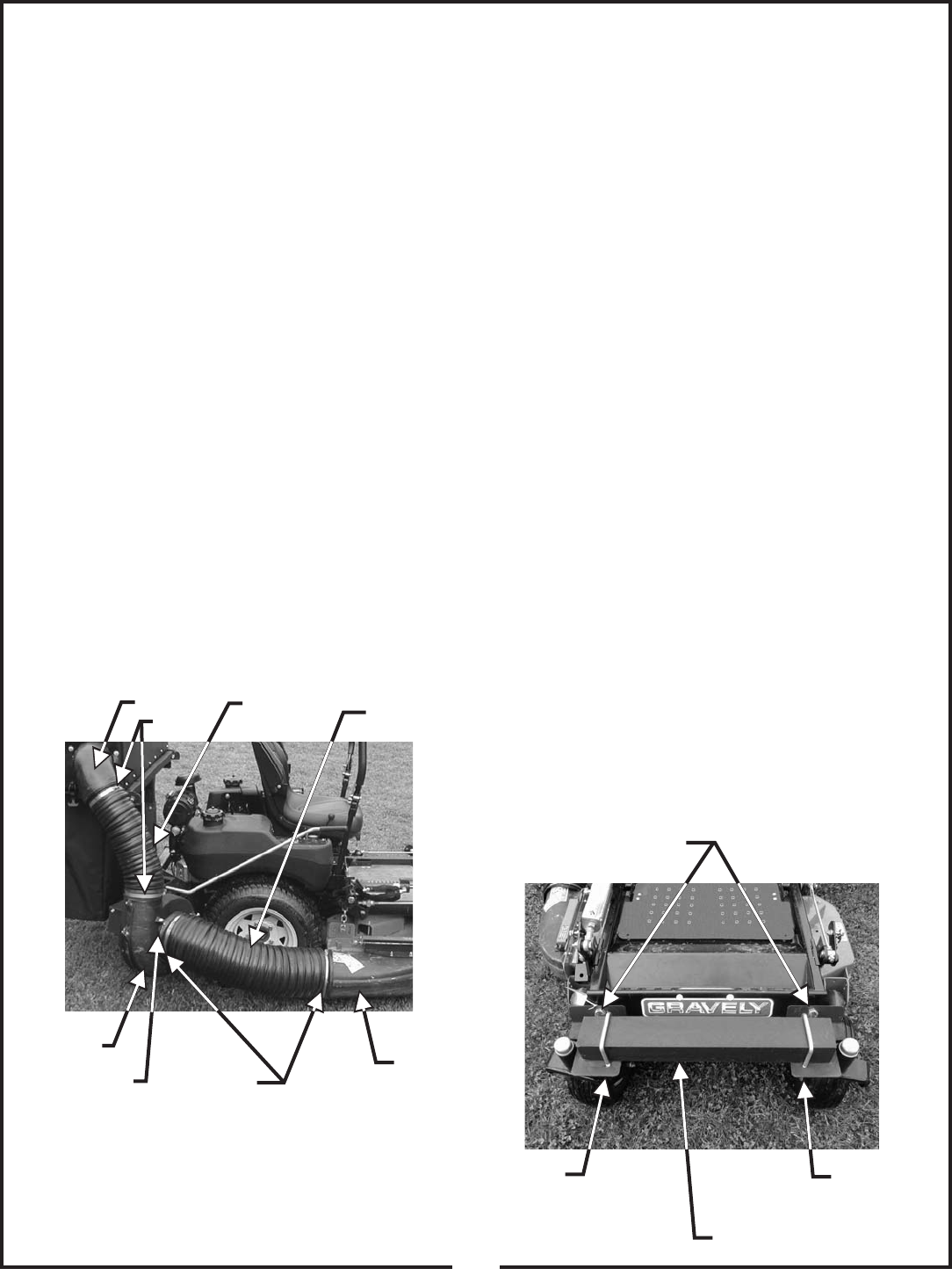
2-12 Attachment Of The Upper Hose
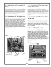
The hoses in steps 2-12 and 2-13 must be cut to fit your
machine. Follow steps 2-12 and 2-13. Do not cut the
hoses until you have tried to fit them on your machine.
Remember that the hoses have to be long enough to
allow for enough clamping surface between the inlet,
blower assembly, and the deck boot.
Fasten the inlet to the plastic top by sliding the inlet from
the inside of the top to the outside and lock into place.
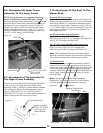
Slide a 5”-6” upper hose clamp P#(J6011) onto both
ends of the 6” upper hose (Figure 21). Then slide one
end of the 6” hose onto the inlet. Make sure there is
about a two-inch overlap between the hose end and the
container inlet. Proceed to slide the opposite end of the
6” hose onto the outlet of the blower assembly. See
Figure 21 for details. Make sure both ends of the hose
are clearly attached to the inlet and the blower assembly
inlet. Tighten the hose clamps.
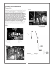
2-13 Attachment Of The Lower Hose
To The Blower Cone
2-14 Attachment Of The Lower Hose
To The Boot
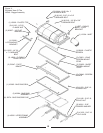
2-15 Front Weight Assembly
Fasten the blower cone P#(E6009) to the blower
housing by using (2) 5/16”-18 x 2-1/2” HHCS P#(K0125)
and (2) 5/16”-18 jam nuts P#(K0120). Slide a 7”-8” hose
clamp P#(J6006) over both ends of the lower hose. Then
proceed to slide the lower hose onto the blower cone.
Tighten the hose clamp. The assembly should look like
Figure 21.
Take the unattached end of the lower hose and slide it
over the circular end of the boot. Use the lower hose
clamp to secure the hose to the boot (Figure 21). Tip:
Before securing clamp rotate hose counter-clockwise
(away from yourself) approximately 1” to add in retaining
boot to mower deck.
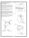
Attach each weight bracket P#(B0188) to the mower’s
front casters by using (1) 3/4”-10 x 1-1/2” HHCS
P#(K0364) and (1) 3/4”-10 nyloc nut P#(K1433) (Figure
22). When installing the 100 lb. weight you should have
another person help position the weight onto a floor jack.
Using the floor jack will make installing the weight much
easier. Lift the weight up to the top of the weight
brackets. Fasten the weight to the weight brackets by
using (1) ½”-13 X 4-1/4” U-Bolt P#(K0331) and (2) ½”-13
flange nuts P#(K1246) per bracket. Once the weight is
secure tighten all nuts. Be sure Weight is centered in
reference to the U-Bolts.
Figure 21.
Figure 22.
Inlet
5”-6”
Clamp
6” Upper
Hose
Boot
Blower
8” Lower
Hose
7”-8”
Clamp
Right
Weight
Bracket
Left
Weight
Bracket
Weight
3/4”-10 X 1-1/2” HHCS
3/4”-10 Nylock Nut
Blower Cone