


12
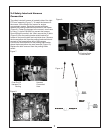
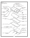
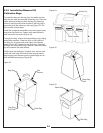
2-10 Attachment Of The Boot To The
Mower Deck
Remove the mower’s deflector shield mount (Figure 20).
Position the notch towards the front of unit and place the
boot hanger P#(B0117) in-between the deflector shield
mount and the mower deck. Fasten by using (3) 3/8”-16
x 1-1/4” HHCS P#(K1192) and the existing 3/8” nuts. The
boot hanger will allow you to switch from collection to
discharge in seconds.
To mount the boot plate P#(B0204) to the boot
P#(E1034) use (3) 3/8”-16 x 1” carriage bolts P#(K1182)
and (3) 3/8”-16 flange nuts P#(K1215).
To mount the boot plate P#(B0190) to the boot
P#(E1113) use (2) 3/8”-16 x 3/4” carriage bolts
P#(K1181) and (2) 3/8”-16 flange nuts P#(K1215).
When bolting the boot and boot plate together,
the head of the bolt is placed from the inside of the boot.
This will prevent grass from collecting on the bolts.
Remove the bolts from that hold the deflector shield in
place so that the boot rod can fasten the boot and boot
plate to the mower deck. Align the holes in the boot plate
to the holes in the deflector shield mount and slide the
boot rod, P#(B2540) for the 60” Deck and P#(B0189) for
the 52” deck, through and fasten by using (1) hair pin
clip P#(K0099).
The Mower’s Deflector Shield Has Been
Removed In The Following Photo For Clarity. Always
have the deflector shield mounted when mowing.
Mounting The Boot Hanger
60” Boot Plate Mounting Instructions
44”, 48” & 52” Boot Plate Mounting Instructions
For All Deck Sizes
Note:
Note:
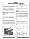
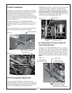
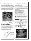
2-8 Attachment Of Upper Frame
Assembly To The Lower Frame
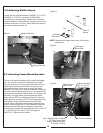
2-9 Attachment of Top Assembly To
The Upper Frame Assembly
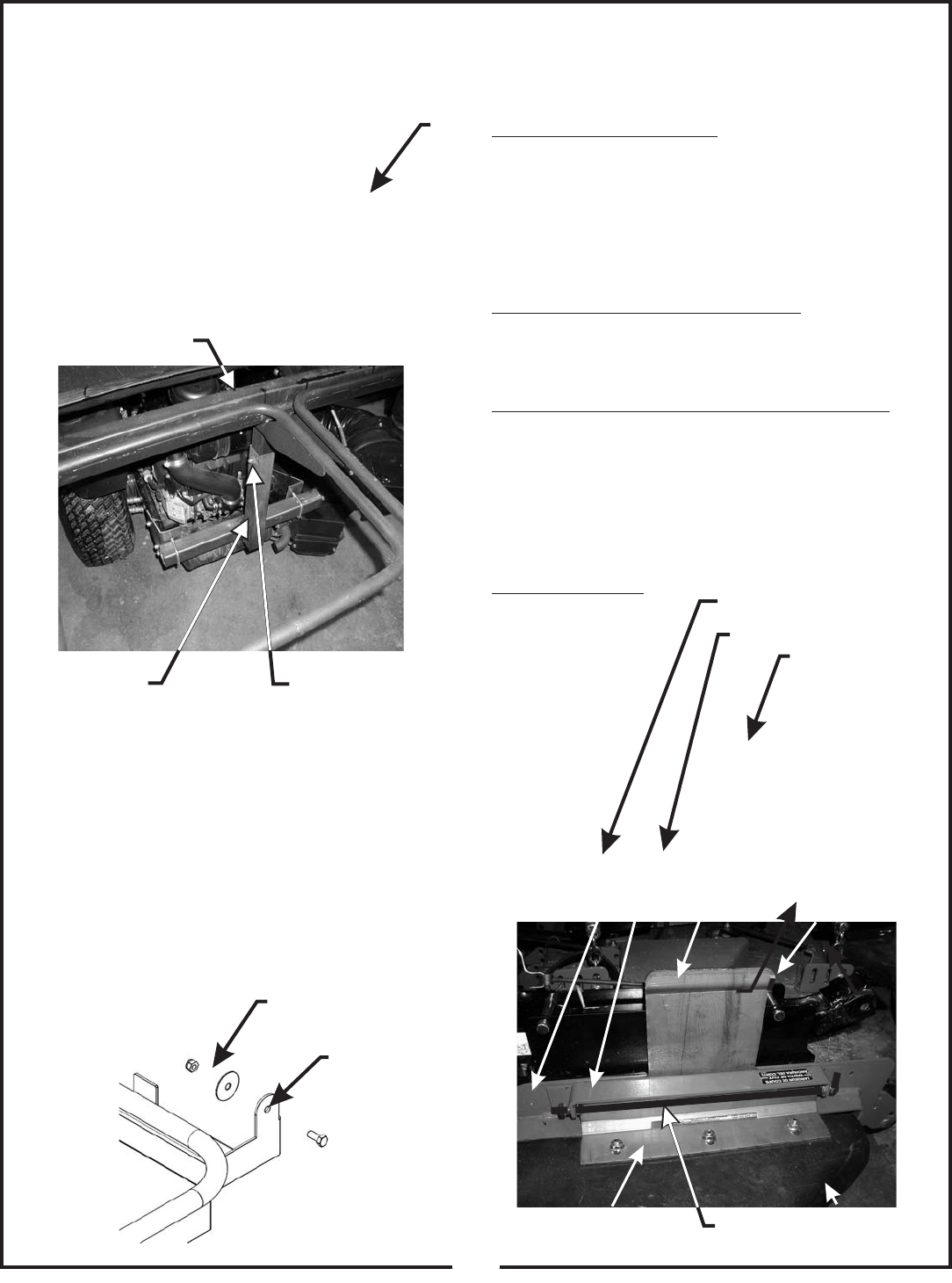
NOTE: During this step, it is suggested that two
people install the top frame to the lower frame.
Using two people to raise the top frame, lift the top frame
above the lower frame making sure the bag frames are
located away from the engine as shown in Figure 18.
Slide the top frame vertical tube into the lower Frame
vertical tube aligning the holes. Insert (1) ½” x 2-1/2”
clevis pin P#(K0133) through the holes and fasten with
(1) 5/32” x 2-5/8” hair pin clip P#(K0088).
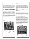
Align the pivot brackets of the top assembly P#(A0551)
to the pivot point on either side of the upper frame
assembly. Place (1) P#(K0041) fender washer between
each pivot point (Figure 19) and fasten each side by
using (1) P#(K1153) 5/16”-18 x 3/4” HHCS and (1)
P#(K1180) 5/16”-18 nyloc nut. When fastening leave nut
slightly loose so that the top can pivot freely.
Lower Frame
½” x 2-1/2” Clevis Pin
5/32” x 2-5/8”
Hair Pin Clip
Top Frame
Figure 18.
Figure 20.
Deflector Shield Mount
Mower Deck
Boot Hanger
Boot
Boot Plate
Notch
Boot Rod
Figure 19.
Top Assembly Here
Fasten Here With
5/16” x 3/4” HHCS
5/16” Nyloc Nut
Fender Washer