


11
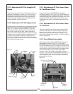
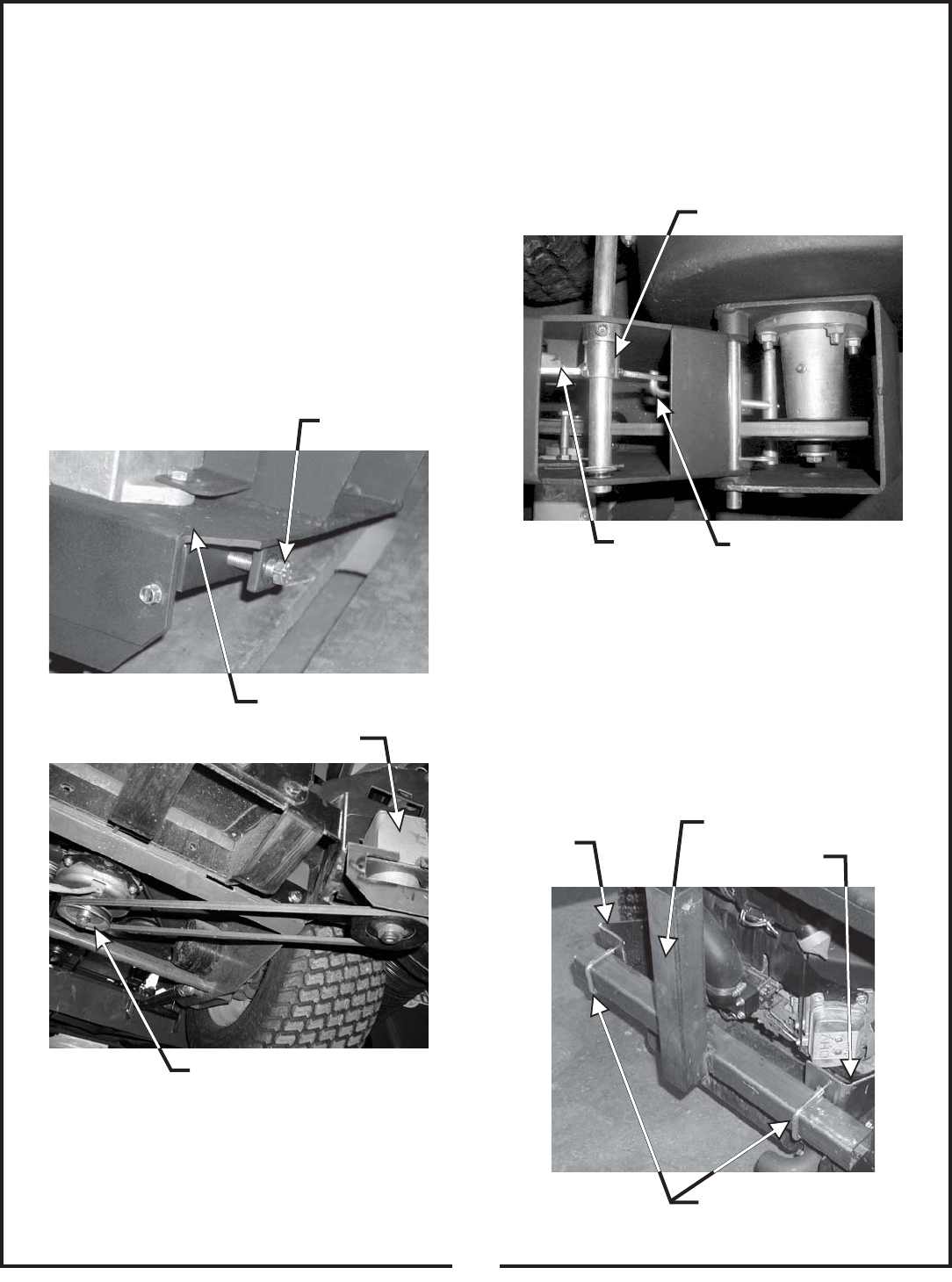
2-6 Cam Assembly Adjustment
The cam assembly P#(A0422), which controls the
blower belt tension, comes from the factory pre-adjusted.
If the belt is too tight or becomes too loose, remove the
hair pin clip P#(K0099) from the belt tension rod
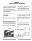
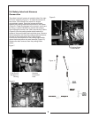
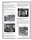
2-5 Belt Installation
Loosen the (2) bolts that secure the gear box assembly
P#(A0429) to the PTO mount plate (Figure 14). Loosen
the adjustment bolt P#(K0348) until the gear box
assembly is at its far left adjustment (the gear box is
moved towards the mower’s engine pulley). Connect the
kevlar cord belt from the engine pulley to the lower gear
box pulley (Figure 15).
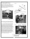
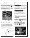
To tension the drive belt, turn the adjustment bolt
clockwise until there is 1” of deflection, with 10-11 lbs. of
pressure between the engine pulley and the gear box
pulley.
Once the correct tension of the belt is achieved, tighten
the (2) bolts that secure the gear box assembly.
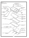
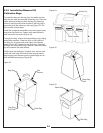
2-7 Attachment Of Lower Frame To
The Frame Brackets.
Using (2) ½”-13 u-bolts P#(K0288) and (2) ½”-13 nyloc
nuts P#(K1247) , attach lower frame to the left and right
frame mount brackets as shown in Figure 17. Make sure
the lower horizontal tube is centered in regards to the
lower frame mount brackets. The lower frame stiffening
bracket is to be positioned towards the engine mower’s
engine.
P#(K0326) and pull the “L” end of the rod out of its hole
in the cam assembly. The tension rod may then be
screwed out to tighten the belt or screwed in to loosen
the belt. Replace the “L” end into the top hole in the cam
and replace the hair pin clip. Adjust the cam stop bolt
P#(K1159) to allow the cam to rotate slightly over center
when the blower is disengaged (Figure 16).
Gear Box Assy.
Adjustment Bolt
PTO Mount Plate
Engine Pulley
Figure 14.
Figure 15.
Cam Assy.
Tension Rod
Figure 16.
Cam Stop
Bolt
Left Frame
Mount Bracket
Lower Frame
Right Frame
Mount Bracket
Lower Frame Centered
In Regards To U-Bolts
Mounted To Frame Brackets
Figure 17.