


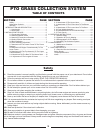
6
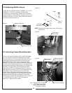
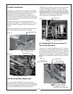
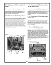
2-2 Attaching Muffler Guard
Locate the two exhaust diverters (P#J0251 w/ 1-1/4” ID,
P#J0250 w/ 1-3/8” ID) and clamp kit P#(X1046)
provided in the hardware bag. Fasten the correct size
exhaust deflector onto the mower’s exhaust and aim the
exhaust as shown in Figure 3. Next, fasten the exhaust
diverter by using the clamp kit.
.
Right and left views are as seen from drivers
perspective.
NOTE:
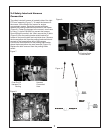
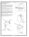
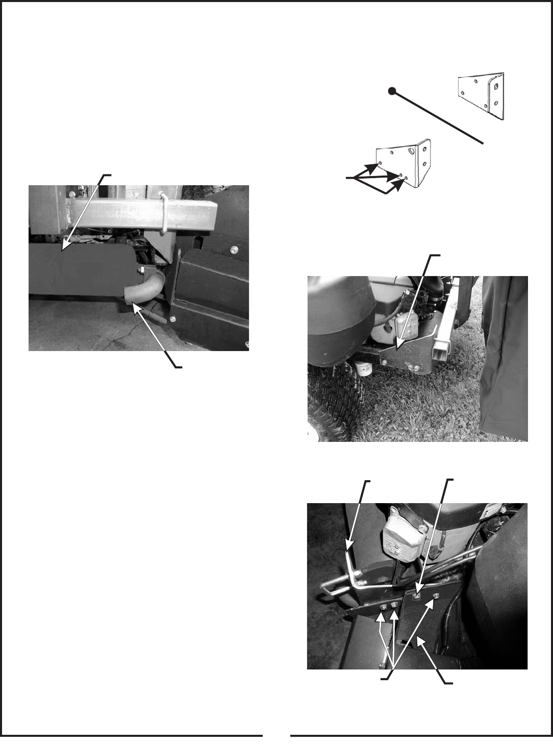
2-3 Attaching Frame Mount Brackets
To mount the frame brackets which support the bagger
unit, you must first remove the existing rear bumper.
This can be done by removing the three bolts and nuts
attaching the bumper to each side. Set the nuts and
bolts aside as they will be used to mount the frame
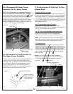
brackets. See Figure 4 for bracket orientation. Mount the
left frame mount bracket (Figure 5) by using three of the
existing bolts and three of the existing nuts. Tighten nuts
and bolts. The right frame mount bracket will mount
along with the PTO arm assembly (Figure 6). Align the
hole pattern on the side of the PTO arm assembly to the
hole pattern on the right frame mount bracket and
mower frame. Place each of the three remaining bolts
one at a time through the PTO Arm assembly, the right
frame bracket and through the existing holes of the
mower frame. Fasten the upper hole by using (1) 3/8”-16
x 1” HHCS P#(K1191) and (1) 3/8”-16 flange nut
P#(K1215). Tighten nuts and bolts.
Figure 4.
Figure 5.
Figure 6.
Left
Right
PTO Arm Assembly
Use 3 Existing Bolts To Mount
PTO Assy. Along With
Right Frame Mount Brkt.
To Tractor’s Frame.
Figure 3.
Mower’s Exhaust
Rear Of
Mower
3 Existing
Bolts Here
Exhaust Diverter
Left Frame
Mount Brkt.
Right Frame
Mount Brkt.
Fasten Here With
3/8” x 1” HHCS
3/8” Flange Nut