


9
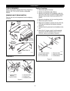
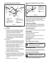
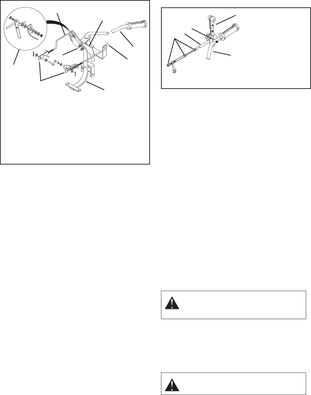
Assemble Steering Brakes (Optional)
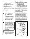
1. Remove nut and bolt from handle brackets.
(Figure 4)
Left Hand Rod:
2. Hook the rear of the left hand brake rod into the
left side of the brake handle weldment. Before
installing on hitch, place the forward end of the
left hand brake rod below muffler brace.
3. Connect the forward end to the pivot plate with a
.375 x .75 clevis pin, (2) .406 x .812 x .065 flat
washers and a .09 x .75 cotter pin. Insert clevis
pin with cotter pin to the outside of adjustment
bracket. (Figure 4)
Right Hand Rod:
1. Hook the rear of the right hand brake rod into the
right outside end of the brake handle weldment.
2. Place the carriage bolt through the brake handle
3. Put two nylon washers on the bolt between the
handle and the handlebar weldment
4. Retain with another nylon washer, rubber washer,
steel washer and lock nut. (Figure 4)
5. Connect the adjustment bracket to the cam lever
arm with a clevis pin, two .406 x .812 x .065 flat
washers and .09 x .75 cotter pin.
6. Push brake handle grip onto handle.
7. Connect the interlock plug to the wiring harness.
8. Fasten the instruction plate and the brake handle
brackets to the rear hitch with the nut and bolt just
removed and an additional 1/2-13 bolt and
locknut.
9. Adjust brakes per
Adjustments
.
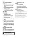
Connect Gear Shift and Directional Control
Rods
Connect the Fwd/Rev and Hi-Lo gear control rods to
the tractor and their respective handles using bushings,
1/4-20 x 1.5 bolts, .281 x .625 x .065 x flat washers and
1/4-20 locknuts. See the gear shift control and
direction control. (Figure 1) and (Figure 5) Adjust per
Owner/Operator Manual.
Install Hubs and Wheels
For Semi-Pneumatic Wheels: install bushings and
wheel/hub assemblies onto tractor axles. For all other
wheels: install hubs to axles and secure wheels to
hubs with hardware provided.
Install Attachment(s)
Install each attachment following instructions provided.
Charge Battery
See Service Battery in
Maintenance
.
Fill Engine Fuel Tank
Add clean fuel to fuel tank. See Engine Manual for
correct type and capacity.
Check Engine Oil
Check and add oil if needed. See Engine Manual for
specifications.
Check Safety Interlock System
Lubricate Pivot Points
Put a drop of engine oil on the pivots of the throttle
lever, the direction control lever, the gear shift lever, the
PTO control, and range shift handle.
Check Function of all Controls
Ensure unit runs and performs properly.
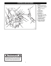
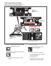
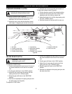
Figure 4
1. Steering Brake
Handle
2. Instruction Plate
3. Left Hand Brake Rod
4. Right Hand Brake
Rod
5. Rear Hitch
6. Adjustment Bracket
7. Bolt and Nut (remove
first)
8. Right Hand Brake
Assembly
1
2
3
4
5
6
7
8
WARNING:
FAILURE OF INTERLOCK,
together with improper operation could
result in death or serious injury.
WARNING:
FAILURE OF CONTROLS
could result in death or serious injury.
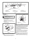
Figure 5
1. Fwd/Rev Control
Handle
2. Right Handlebar
3. Hand Lever Pivot
4. Fwd/Rev Control
Rod
5. Adjust and Jam
Nuts
1
2
3
4
5