


8
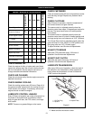
TOOLS REQUIRED
Phillips Screwdriver, Needle Nose Pliers, Open-End
Wrench: 3/8, 7/16, 9/16 & 3/4 and or Adjustable
Wrench
REMOVE UNIT FROM CARTON
Remove the unit and components from the shipping
container.
ASSEMBLY
Position Handlebar
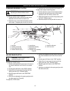
1. Disconnect Ignition Harness.
2. Position the handlebar right side up.
3. Move the left handle of the handlebar under the
right side of the frame, across the engine and out
between the left side of the frame and the PTO
control.
4. Rotate the handlebar into the mounting position.
5. Reconnect ignition harness.
6. Retain the handlebar in position with four 3/8-16 x
1.25 bolts and locknuts and tighten hardware
(Figure 2).
7. Connect the wiring harness from handlebar to the
unit.
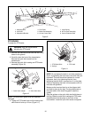
8. Mount the Hi-Lo gear control handle assembly
and pivot to the left handlebar with a 1/2-13 x
3.50 bolt, locknut, and washer (Figure 3).
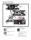
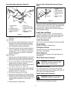
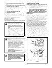
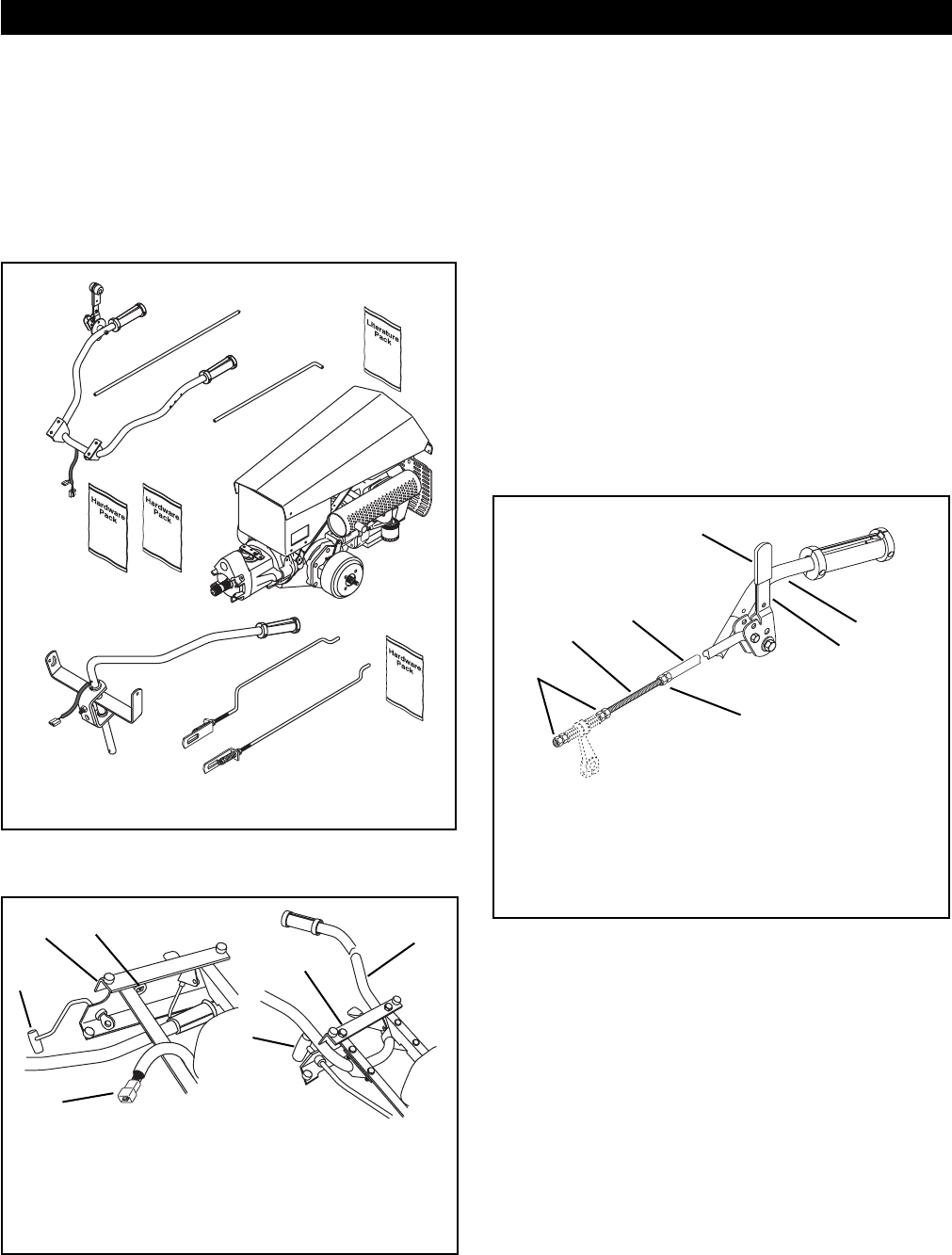
ASSEMBLY
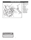
Figure 1
Handlebar
Assembly
Fwd-Rev
Control
Rod
Hi-Lo
Control Rod
Tractor
Assembly
Optional
Brake Handle
Assembly
Brake Rod, RH
Brake Rod, LH
DH0010
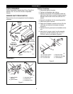
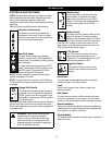
Figure 2
1. Ignition Switch
Harness
2. Ignition Switch
3. Instrument Panel
4. Control Lever
5. Handlebar (Left)
1
2
3
4
5
3
4
DH0020
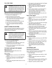
Figure 3
1. Hi-Lo Control Handle
2. Brake Handle Grip
3. Hi-Lo Control Rod
4. Extension Rod
5. Adjust and Jam Nuts
6. Left Handlebar
1
2
3
4
5
5
6
DH0040